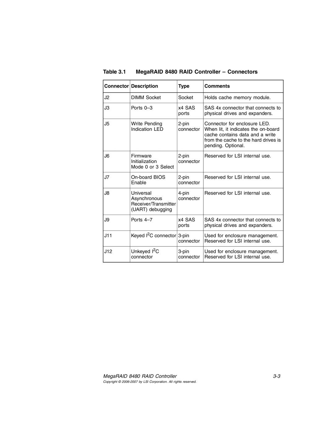
MegaRAID 8480 specifications
The IBM MegaRAID 8480 is a high-performance RAID (Redundant Array of Independent Disks) controller designed for enterprise-class storage environments. It delivers advanced data protection, high availability, and exceptional scalability, making it an ideal choice for businesses that require robust data management solutions.One of the main features of the IBM MegaRAID 8480 is its support for both SAS (Serial Attached SCSI) and SATA (Serial ATA) drives, providing flexibility in storage configurations. This controller supports up to 128 devices, allowing organizations to build large, efficient storage arrays that can accommodate extensive data needs.
The MegaRAID 8480 utilizes advanced RAID levels, including RAID 0, 1, 5, 6, 10, 50, and 60, enabling users to select the level of data redundancy and performance that best fits their specific requirements. The controller also supports online capacity expansion and RAID level migration, ensuring that users can seamlessly adapt their storage configurations as their business evolves.
In terms of performance, the MegaRAID 8480 is equipped with 8GB of DDR4 cache memory, which significantly enhances data access speeds and provides improved I/O performance. With the ability to process a large number of transactions simultaneously, this controller is well-suited for demanding enterprise applications, such as database management systems and virtualized environments.
To further enhance data protection, the MegaRAID 8480 features battery-backed write cache technology. This ensures that data in the cache is not lost in the event of a power failure, safeguarding critical information. Furthermore, the MegaRAID SafeStore technology offers additional protection through encryption-key management, which helps safeguard sensitive data from unauthorized access.
Another notable characteristic is the intuitive management interface provided by the MegaRAID Storage Manager software. This tool streamlines storage monitoring and enables users to easily manage their RAID configurations. Additionally, the controller supports advanced diagnostic features that assist administrators in identifying and resolving potential issues before they escalate.
The IBM MegaRAID 8480 is designed for the modern data-driven enterprise, combining performance, reliability, and scalability into a comprehensive storage solution. With its robust set of features and cutting-edge technology, it empowers organizations to enhance their data management strategies while ensuring that their critical applications remain available and secure. This makes the MegaRAID 8480 a standout choice for businesses seeking to future-proof their storage infrastructure.
