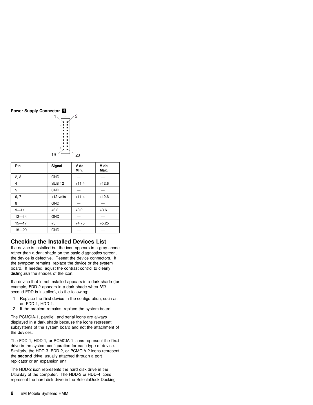
Power Supply Connector | .5/ |
1 | 2 |
|
| 19 |
| 20 |
|
|
|
|
|
|
|
Pin |
| Signal |
| V dc | V dc |
|
|
|
| Min. | Max. |
|
|
|
|
|
|
2, | 3 | GND |
| — | — |
|
|
|
|
|
|
4 |
| SUB | 12 | +11.4 | +12.6 |
|
|
|
|
|
|
5 |
| GND |
| — | — |
|
|
|
|
|
|
6, | 7 | +12 | volts | +11.4 | +12.6 |
|
|
|
|
|
|
8 |
| GND |
| — | — |
|
|
|
|
| |
+3.3 |
| +3.0 | +3.6 | ||
|
|
|
|
| |
GND |
| — | — | ||
|
|
|
|
| |
+5 |
| +4.75 | +5.25 | ||
|
|
|
|
| |
GND |
| — | — | ||
|
|
|
|
|
|
Checking | the | Installed | Devices | List |
|
|
|
| |||
If a device is installed | but | the | icon | appears in a gray shade | |||||||
rather | than | a | dark | shade | on the | basic | diagnostics screen, | ||||
the device is defective. Reseat the | device | connectors. If | |||||||||
the symptom | remains, | replace | the device or the system | ||||||||
board. If needed, adjust the contrast control to clearly | |||||||||||
distinguish | the | shades | of | the | icon. |
|
|
| |||
If a device that is not | installed | appears in | a dark shade (for | ||||||||
example, | dark | shadeNO | when |
| |||||||
second | FDD | is | installed), | do | the |
| following: |
| |||
1. | Replace | firstthe device in | the configuration, such as |
| an |
| |
2. | If the problem remains, | replace the system board. | |
The
subsystems of the system board | and not the attachment of | |
the | devices. |
|
The | representfirst the | |
drive in the system configuration for each type of device. Similarly, the
thesecond drive, usually attached through a port replicator or an expansion unit.
The
8 IBM Mobile Systems HMM