Table 27. Removal steps of LCD unit (continued)
2
2 |
| 2 |
2 |
| |
| 2 | |
|
| |
2 | 2 | 2 |
|
| 2 |
2 | 2 |
|
When installing: Make sure that the connector is attached firmly to the system board.
2020 LCD bezel assembly
For access, remove these FRUs in order:
•“1010 Battery pack” on page 50
•“1020 Bottom slot cover” on page 51
•“1040 Hard disk drive or solid state drive assembly” on page 53
•“1070 Keyboard” on page 57
•“1090 Top case assembly” on page 60
•“1130 System board assembly, fan assembly, and backup battery” on page 65
•“2010 LCD unit” on page 71
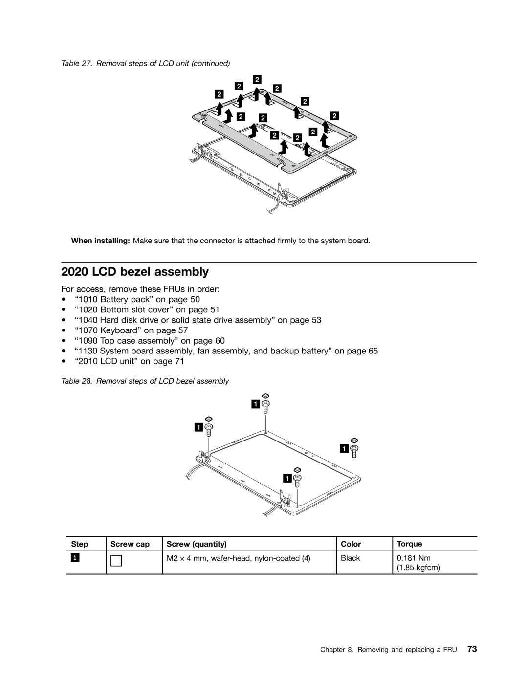
Table 28. Removal steps of LCD bezel assembly
1
1
1
1![]()
| Step | Screw cap | Screw (quantity) | Color | Torque | |
|
|
|
|
|
|
|
|
|
|
| M2 × 4 mm, | Black | 0.181 Nm |
| 1 |
|
| |||
|
|
|
|
|
| (1.85 kgfcm) |
|
|
|
|
|
|
|
Chapter 8. Removing and replacing a FRU 73