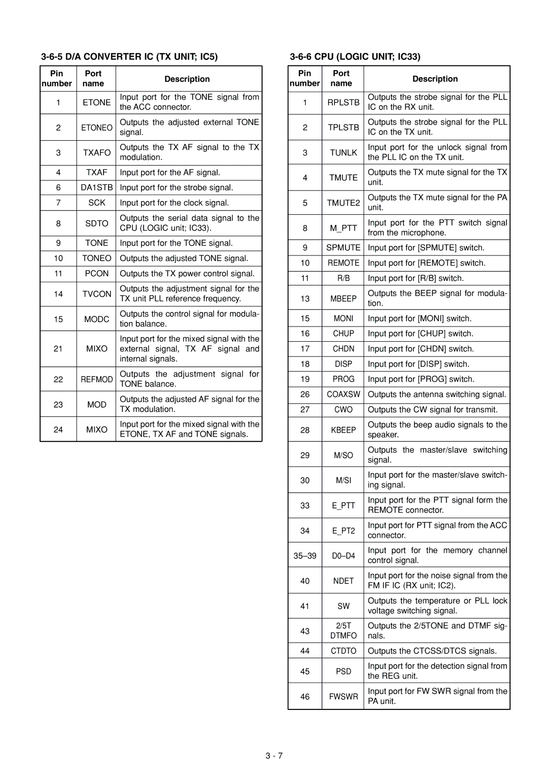
3-6-5 D/A CONVERTER IC (TX UNIT; IC5)
Pin | Port | Description | |
number | name | ||
| |||
|
|
| |
1 | ETONE | Input port for the TONE signal from | |
the ACC connector. | |||
|
| ||
|
|
| |
2 | ETONEO | Outputs the adjusted external TONE | |
signal. | |||
|
|
| |
3 | TXAFO | Outputs the TX AF signal to the TX | |
modulation. | |||
|
| ||
|
|
| |
4 | TXAF | Input port for the AF signal. | |
|
|
| |
6 | DA1STB | Input port for the strobe signal. | |
|
|
| |
7 | SCK | Input port for the clock signal. | |
|
|
| |
8 | SDTO | Outputs the serial data signal to the | |
CPU (LOGIC unit; IC33). | |||
|
| ||
|
|
| |
9 | TONE | Input port for the TONE signal. | |
|
|
| |
10 | TONEO | Outputs the adjusted TONE signal. | |
|
|
| |
11 | PCON | Outputs the TX power control signal. | |
|
|
| |
14 | TVCON | Outputs the adjustment signal for the | |
TX unit PLL reference frequency. | |||
|
| ||
|
|
| |
15 | MODC | Outputs the control signal for modula- | |
tion balance. | |||
|
| ||
|
|
| |
|
| Input port for the mixed signal with the | |
21 | MIXO | external signal, TX AF signal and | |
|
| internal signals. | |
|
|
| |
22 | REFMOD | Outputs the adjustment signal for | |
TONE balance. | |||
|
|
| |
23 | MOD | Outputs the adjusted AF signal for the | |
TX modulation. | |||
|
| ||
|
|
| |
24 | MIXO | Input port for the mixed signal with the | |
ETONE, TX AF and TONE signals. | |||
|
| ||
|
|
|
3-6-6 CPU (LOGIC UNIT; IC33)
Pin | Port | Description | |
number | name | ||
| |||
|
|
| |
1 | RPLSTB | Outputs the strobe signal for the PLL | |
IC on the RX unit. | |||
|
| ||
|
|
| |
2 | TPLSTB | Outputs the strobe signal for the PLL | |
IC on the TX unit. | |||
|
| ||
|
|
| |
3 | TUNLK | Input port for the unlock signal from | |
the PLL IC on the TX unit. | |||
|
| ||
|
|
| |
4 | TMUTE | Outputs the TX mute signal for the TX | |
unit. | |||
|
| ||
|
|
| |
5 | TMUTE2 | Outputs the TX mute signal for the PA | |
unit. | |||
|
| ||
|
|
| |
8 | M_PTT | Input port for the PTT switch signal | |
from the microphone. | |||
|
| ||
|
|
| |
9 | SPMUTE | Input port for [SPMUTE] switch. | |
|
|
| |
10 | REMOTE | Input port for [REMOTE] switch. | |
|
|
| |
11 | R/B | Input port for [R/B] switch. | |
|
|
| |
13 | MBEEP | Outputs the BEEP signal for modula- | |
tion. | |||
|
| ||
|
|
| |
15 | MONI | Input port for [MONI] switch. | |
|
|
| |
16 | CHUP | Input port for [CHUP] switch. | |
|
|
| |
17 | CHDN | Input port for [CHDN] switch. | |
|
|
| |
18 | DISP | Input port for [DISP] switch. | |
|
|
| |
19 | PROG | Input port for [PROG] switch. | |
|
|
| |
26 | COAXSW | Outputs the antenna switching signal. | |
|
|
| |
27 | CWO | Outputs the CW signal for transmit. | |
|
|
| |
28 | KBEEP | Outputs the beep audio signals to the | |
speaker. | |||
|
| ||
|
|
| |
29 | M/SO | Outputs the master/slave switching | |
signal. | |||
|
| ||
|
|
| |
30 | M/SI | Input port for the master/slave switch- | |
ing signal. | |||
|
| ||
|
|
| |
33 | E_PTT | Input port for the PTT signal form the | |
REMOTE connector. | |||
|
| ||
|
|
| |
34 | E_PT2 | Input port for PTT signal from the ACC | |
connector. | |||
|
| ||
|
|
| |
Input port for the memory channel | |||
control signal. | |||
|
| ||
|
|
| |
40 | NDET | Input port for the noise signal from the | |
FM IF IC (RX unit; IC2). | |||
|
| ||
|
|
| |
41 | SW | Outputs the temperature or PLL lock | |
voltage switching signal. | |||
|
| ||
|
|
| |
43 | 2/5T | Outputs the 2/5TONE and DTMF sig- | |
DTMFO | nals. | ||
| |||
|
|
| |
44 | CTDTO | Outputs the CTCSS/DTCS signals. | |
|
|
| |
45 | PSD | Input port for the detection signal from | |
the REG unit. | |||
|
| ||
|
|
| |
46 | FWSWR | Input port for FW SWR signal from the | |
PA unit. | |||
|
| ||
|
|
|
3 - 7