3-6 PORT ALLOCATIONS
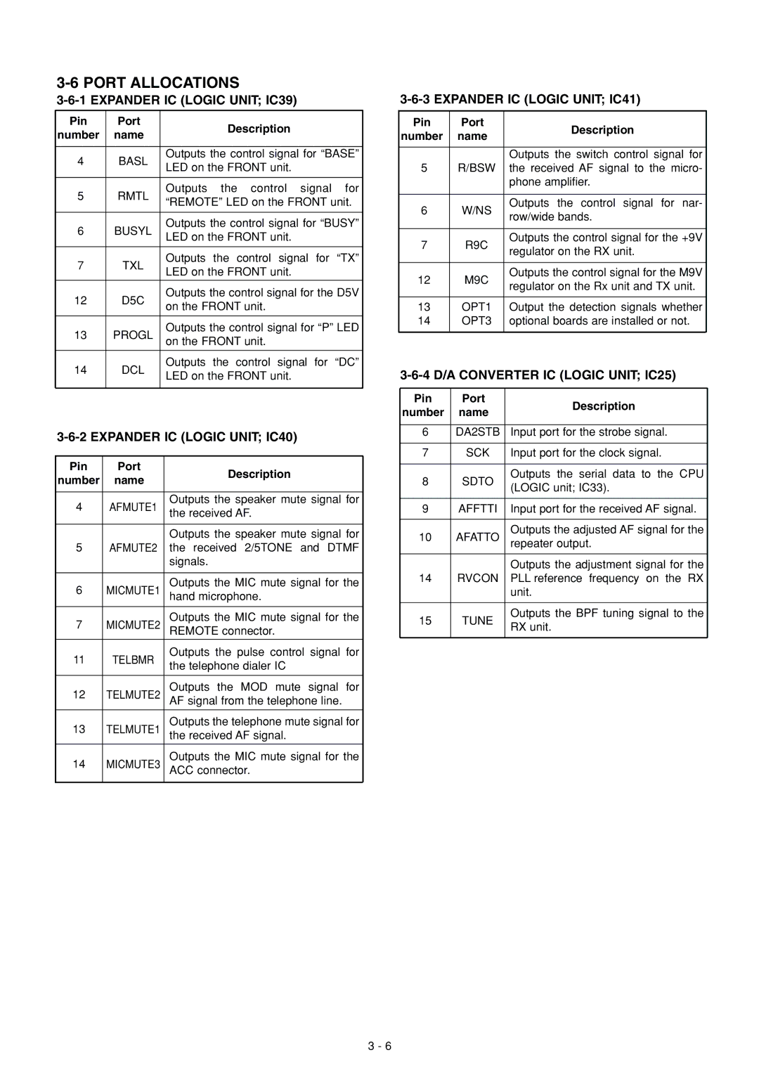
3-6-1 EXPANDER IC (LOGIC UNIT; IC39)
Pin | Port |
| Description | |
number | name |
| ||
|
| |||
|
|
| ||
4 | BASL | Outputs the control signal for “BASE” | ||
LED on the FRONT unit. | ||||
|
| |||
|
|
|
| |
5 | RMTL | Outputs | the control signal for | |
“REMOTE” LED on the FRONT unit. | ||||
|
| |||
|
|
| ||
6 | BUSYL | Outputs the control signal for “BUSY” | ||
LED on the FRONT unit. | ||||
|
| |||
|
|
|
| |
7 | TXL | Outputs | the control signal for “TX” | |
LED on the FRONT unit. | ||||
|
| |||
|
|
| ||
12 | D5C | Outputs the control signal for the D5V | ||
on the FRONT unit. | ||||
|
| |||
|
|
| ||
13 | PROGL | Outputs the control signal for “P” LED | ||
on the FRONT unit. | ||||
|
| |||
|
|
|
| |
14 | DCL | Outputs | the control signal for “DC” | |
LED on the FRONT unit. | ||||
|
| |||
|
|
|
| |
3-6-2 EXPANDER IC (LOGIC UNIT; IC40)
Pin | Port | Description | |
number | name | ||
| |||
|
|
| |
4 | AFMUTE1 | Outputs the speaker mute signal for | |
the received AF. | |||
|
| ||
|
|
| |
|
| Outputs the speaker mute signal for | |
5 | AFMUTE2 | the received 2/5TONE and DTMF | |
|
| signals. | |
|
|
| |
6 | MICMUTE1 | Outputs the MIC mute signal for the | |
hand microphone. | |||
|
|
| |
7 | MICMUTE2 | Outputs the MIC mute signal for the | |
REMOTE connector. | |||
11 | TELBMR | Outputs the pulse control signal for | |
the telephone dialer IC | |||
|
| ||
|
|
| |
12 | TELMUTE2 | Outputs the MOD mute signal for | |
AF signal from the telephone line. | |||
|
|
| |
13 | TELMUTE1 | Outputs the telephone mute signal for | |
the received AF signal. | |||
|
|
| |
14 | MICMUTE3 | Outputs the MIC mute signal for the | |
ACC connector. | |||
|
|
|
3-6-3 EXPANDER IC (LOGIC UNIT; IC41)
Pin | Port | Description | |
number | name | ||
| |||
|
|
| |
|
| Outputs the switch control signal for | |
5 | R/BSW | the received AF signal to the micro- | |
|
| phone amplifier. | |
|
|
| |
6 | W/NS | Outputs the control signal for nar- | |
row/wide bands. | |||
|
| ||
|
|
| |
7 | R9C | Outputs the control signal for the +9V | |
regulator on the RX unit. | |||
|
| ||
|
|
| |
12 | M9C | Outputs the control signal for the M9V | |
regulator on the Rx unit and TX unit. | |||
|
| ||
|
|
| |
13 | OPT1 | Output the detection signals whether | |
14 | OPT3 | optional boards are installed or not. | |
|
|
|
3-6-4 D/A CONVERTER IC (LOGIC UNIT; IC25)
Pin | Port | Description | |
number | name | ||
| |||
|
|
| |
6 | DA2STB | Input port for the strobe signal. | |
|
|
| |
7 | SCK | Input port for the clock signal. | |
|
|
| |
8 | SDTO | Outputs the serial data to the CPU | |
(LOGIC unit; IC33). | |||
|
| ||
|
|
| |
9 | AFFTTI | Input port for the received AF signal. | |
|
|
| |
10 | AFATTO | Outputs the adjusted AF signal for the | |
repeater output. | |||
|
| ||
|
|
| |
|
| Outputs the adjustment signal for the | |
14 | RVCON | PLL reference frequency on the RX | |
|
| unit. | |
|
|
| |
15 | TUNE | Outputs the BPF tuning signal to the | |
RX unit. | |||
|
| ||
|
|
|
3 - 6