SECTION 6 OPTION UNIT INSTALLATION
6-1 Opening the repeater’s case
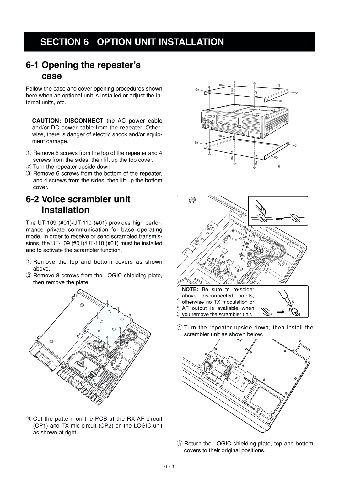
Follow the case and cover opening procedures shown here when an optional unit is installed or adjust the in- ternal units, etc.
CAUTION: DISCONNECT the AC power cable and/or DC power cable from the repeater. Other- wise, there is danger of electric shock and/or equip- ment damage.
qRemove 6 screws from the top of the repeater and 4 screws from the sides, then lift up the top cover.
wTurn the repeater upside down.
eRemove 6 screws from the bottom of the repeater, and 4 screws from the sides, then lift up the bottom cover.
6-2 Voice scrambler unit installation
The
qRemove the top and bottom covers as shown above.
wRemove 8 screws from the LOGIC shielding plate, then remove the plate.
eCut the pattern on the PCB at the RX AF circuit (CP1) and TX mic circuit (CP2) on the LOGIC unit as shown at right.
NOTE:![]() Be sure to
Be sure to ![]() solder
solder![]() available when you remove the scrambler unit.
available when you remove the scrambler unit.
rTurn the repeater upside down, then install the scrambler unit as shown below.
tReturn the LOGIC shielding plate, top and bottom covers to their original positions.
6 - 1