IC-R8500 specifications
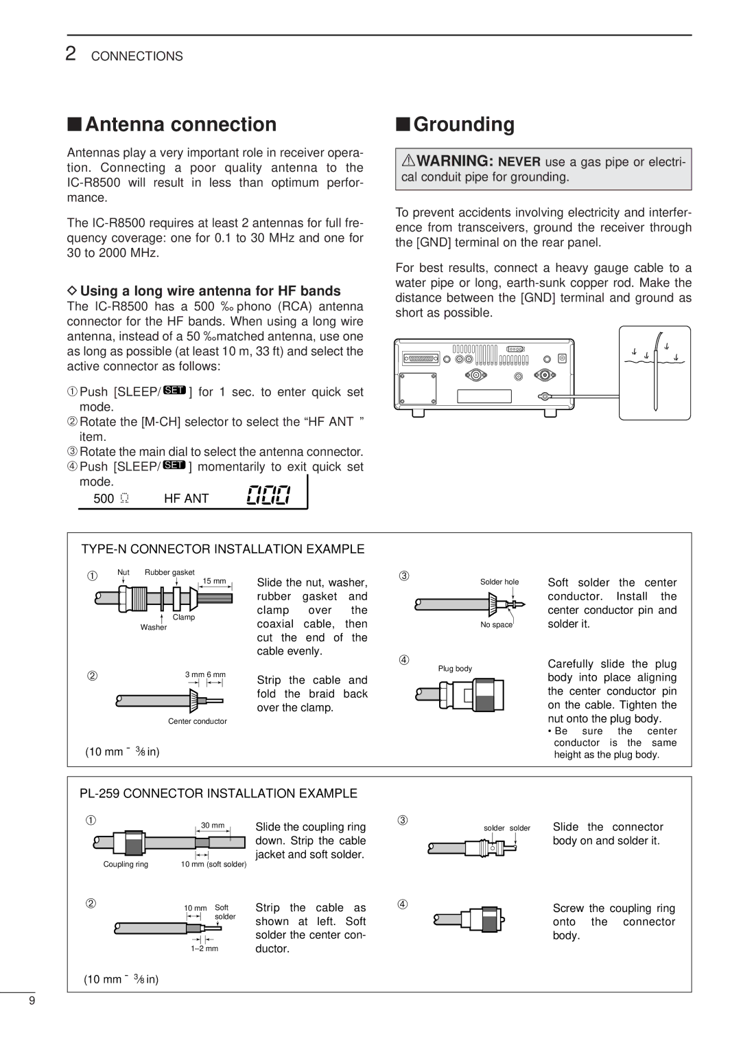
The Icom IC-R8500 is a highly regarded general-purpose receiver that has made its mark among amateur radio enthusiasts and professionals alike. This versatile communication receiver is known for its wide frequency coverage, advanced features, and robust design, making it a valuable tool for various applications, including shortwave listening, public safety communication, and aircraft monitoring.One of the standout features of the IC-R8500 is its extensive frequency coverage. It spans a range from 0.1 MHz to 3 GHz, allowing users to access a wide spectrum of signals. The receiver includes coverage of HF, VHF, UHF, and even microwave bands, making it suitable for listening to everything from amateur radio transmissions to satellite communications.
The receiver employs a high-performance double-conversion superheterodyne architecture, which contributes to its excellent sensitivity and selectivity. The advanced RF circuitry minimizes interference and enhances the clarity of received signals. Users can expect outstanding audio quality and a wide dynamic range, even in challenging reception conditions.
Digital Signal Processing (DSP) is another key technology incorporated into the IC-R8500. The DSP capabilities allow users to apply noise reduction and filtering techniques to improve the quality of the received audio. Features such as automatic notch filtering and IF filtering help eliminate unwanted noise, enhancing the listening experience.
The IC-R8500 is equipped with a large, easy-to-read LCD display that provides information on frequency, mode, signal strength, and other essential parameters. The user-friendly interface simplifies operation, allowing quick access to various settings and functions. Additionally, the receiver supports various modulation modes, including AM, FM, SSB, and CW, catering to different listening preferences.
For those seeking enhanced connectivity, the IC-R8500 offers multiple options, including an audio output jack, and external speaker connections. It also has a built-in memory function, allowing users to store and recall favorite frequencies easily. The receiver can be controlled via a computer interface, offering versatility for advanced users and programmers.
In summary, the Icom IC-R8500 stands out for its wide frequency range, superior sensitivity, and advanced features powered by DSP technology. Its robust construction and user-friendly design make it a favorite among communications enthusiasts seeking a reliable and versatile receiver for various applications. Whether for hobbyist listening or professional use, the IC-R8500 remains a top choice in the world of radio receivers.

