9

MAINTENANCE SCHEDULE

BELT ADJUSTMENT _________________________________

Daily or Before Each Operation

Weekly

Monthly

3/500 *

12/2000 *

￿Check for oil leaks.

￿Check lubricant level. Fill as needed.

￿Drain receiver tank condensate (if automatic draining device is not provided). Open manual drain valve and collect and dispose of condensate accordingly.

￿Check for unusual noise and vibration.

￿Ensure beltguards and covers are securely in place.

￿Ensure engine (if supplied) is filled with fuel and lubricant according to the manufacturer’s recommendations.

￿Ensure area around compressor is free from rags, tools, debris, and flammable or explosive materials.

￿Observe operation of safety/relief valves while the compressor is running. Replace safety/relief valves that do not operate freely.

￿Inspect air filter element(s). Clean if necessary.

￿Inspect for air leaks. Squirt soapy water around joints during compressor operation and watch for bubbles.

￿Check tightness of screws and bolts. Tighten as needed.

￿Inspect drive belts. Adjust if necessary.

￿Clean exterior.

￿Change petroleum lubricant while crankcase is warm.

￿Drain compressor oil and clean oil sight glass

￿Install maintenance pak

— or —

￿Change synthetic lubricant while crankcase is warm.

￿Replace filter element.

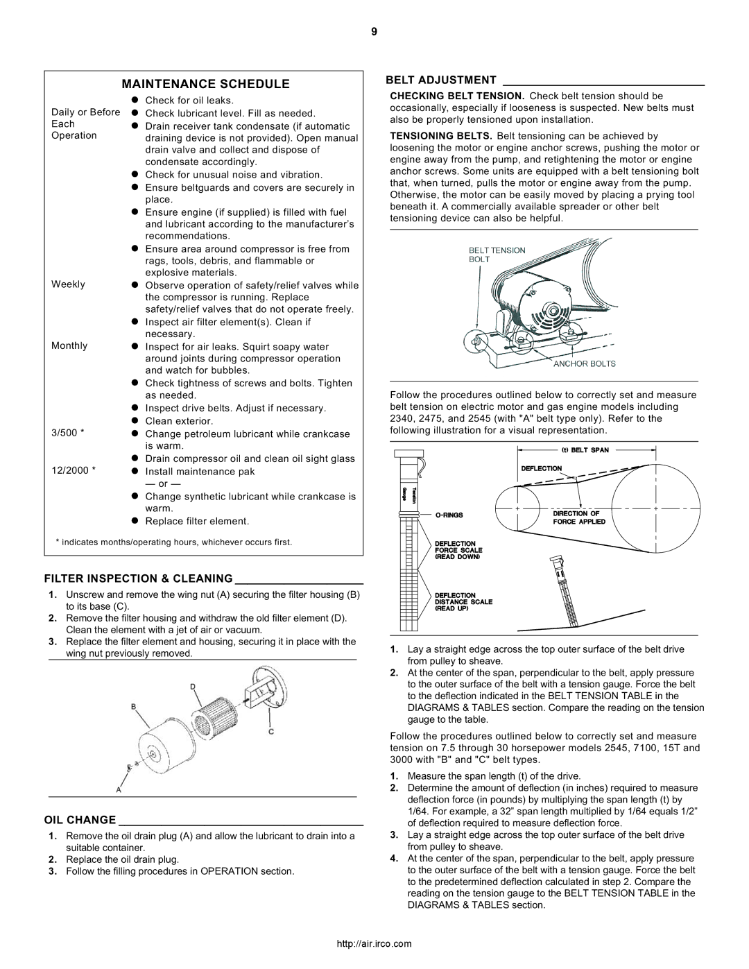
CHECKING BELT TENSION. Check belt tension should be occasionally, especially if looseness is suspected. New belts must also be properly tensioned upon installation.

TENSIONING BELTS. Belt tensioning can be achieved by loosening the motor or engine anchor screws, pushing the motor or engine away from the pump, and retightening the motor or engine anchor screws. Some units are equipped with a belt tensioning bolt that, when turned, pulls the motor or engine away from the pump. Otherwise, the motor can be easily moved by placing a prying tool beneath it. A commercially available spreader or other belt tensioning device can also be helpful.

Follow the procedures outlined below to correctly set and measure belt tension on electric motor and gas engine models including 2340, 2475, and 2545 (with "A" belt type only). Refer to the following illustration for a visual representation.

* indicates months/operating hours, whichever occurs first.

FILTER INSPECTION & CLEANING _____________________

1.Unscrew and remove the wing nut (A) securing the filter housing (B) to its base (C).

2.Remove the filter housing and withdraw the old filter element (D). Clean the element with a jet of air or vacuum.

3.Replace the filter element and housing, securing it in place with the wing nut previously removed.

OIL CHANGE ________________________________________

1.Remove the oil drain plug (A) and allow the lubricant to drain into a suitable container.

2.Replace the oil drain plug.

3.Follow the filling procedures in OPERATION section.

1.Lay a straight edge across the top outer surface of the belt drive from pulley to sheave.

2.At the center of the span, perpendicular to the belt, apply pressure to the outer surface of the belt with a tension gauge. Force the belt to the deflection indicated in the BELT TENSION TABLE in the DIAGRAMS & TABLES section. Compare the reading on the tension gauge to the table.

Follow the procedures outlined below to correctly set and measure tension on 7.5 through 30 horsepower models 2545, 7100, 15T and 3000 with "B" and "C" belt types.

1.Measure the span length (t) of the drive.

2.Determine the amount of deflection (in inches) required to measure deflection force (in pounds) by multiplying the span length (t) by 1/64. For example, a 32” span length multiplied by 1/64 equals 1/2” of deflection required to measure deflection force.

3.Lay a straight edge across the top outer surface of the belt drive from pulley to sheave.

4.At the center of the span, perpendicular to the belt, apply pressure to the outer surface of the belt with a tension gauge. Force the belt to the predetermined deflection calculated in step 2. Compare the reading on the tension gauge to the BELT TENSION TABLE in the DIAGRAMS & TABLES section.

http://air.irco.com

Page 9
Image 9
Ingersoll-Rand 2340, 3000, 7100, 2475, 15T Maintenance Schedule, Belt Adjustment, Filter Inspection & Cleaning, OIL Change

7100, 2475, 2340, 3000, 2545 specifications

Ingersoll-Rand is a recognized leader in the field of industrial tools and compressed air solutions, and among their notable product offerings are the air compressor models: 15T, 2545, 3000, 2340, and 2475. These models are engineered to meet various industrial needs, providing reliable performance with enhanced efficiency and durability.

The Ingersoll-Rand 15T is a compact yet powerful rotary screw air compressor designed for small- to medium-sized operations. It features a robust build along with a user-friendly interface, allowing operators to easily adjust settings. Known for its low noise levels and energy efficiency, the 15T is ideal for applications requiring consistent air supply in a quiet environment.

The 2545 model is a workhorse in the family, recognized for its high output and extensive capabilities. It leverages advanced rotary screw technology, which provides continuous air flow while minimizing energy consumption. With its high-efficiency air end, the 2545 significantly reduces operating costs, making it suitable for heavy-duty tasks in demanding environments.

The Ingersoll-Rand 3000 is a portable solution that combines mobility with powerful performance. Featuring a rugged design, the 3000 is well-suited for construction sites and outdoor applications. It comes equipped with a reliable cooling system, enabling it to operate effectively in varying temperatures. Its compact design allows it to fit easily in tight spaces while providing ample air power.

The 2340 model emphasizes versatility and reliability, often used in automotive, manufacturing, and energy industries. It offers advanced features such as built-in control systems and service indicators, making maintenance simpler. This model is highly regarded for its reliability, which minimizes downtime and maximizes productivity.

Lastly, the Ingersoll-Rand 2475 is a robust compressor characterized by high flow rates and exceptional durability. It is engineered for large-scale applications, supporting heavy machinery and pneumatic tools. It incorporates sophisticated technology that ensures low noise emissions and energy-efficient operation, catering to workplaces that prioritize eco-friendliness.

Incorporating features like variable-speed drives, advanced cooling systems, and comprehensive monitoring technology, all these models exemplify the commitment of Ingersoll-Rand to innovation and user-centric designs. Whether for small workshops or large industrial operations, these compressors deliver unmatched performance and reliability, making them essential tools in various applications. Their consistent engineering excellence ensures that users can depend on Ingersoll-Rand products for their compressed air needs.