Ingersoll-Rand 7100 Pressure Switch Adjustment, Starting Unloading System, Auxiliary Valve, Psig

Models: 7100 2475 2340 3000 2545 15T

1 56
Download 56 pages 14.76 Kb
Page 7
Image 7

7

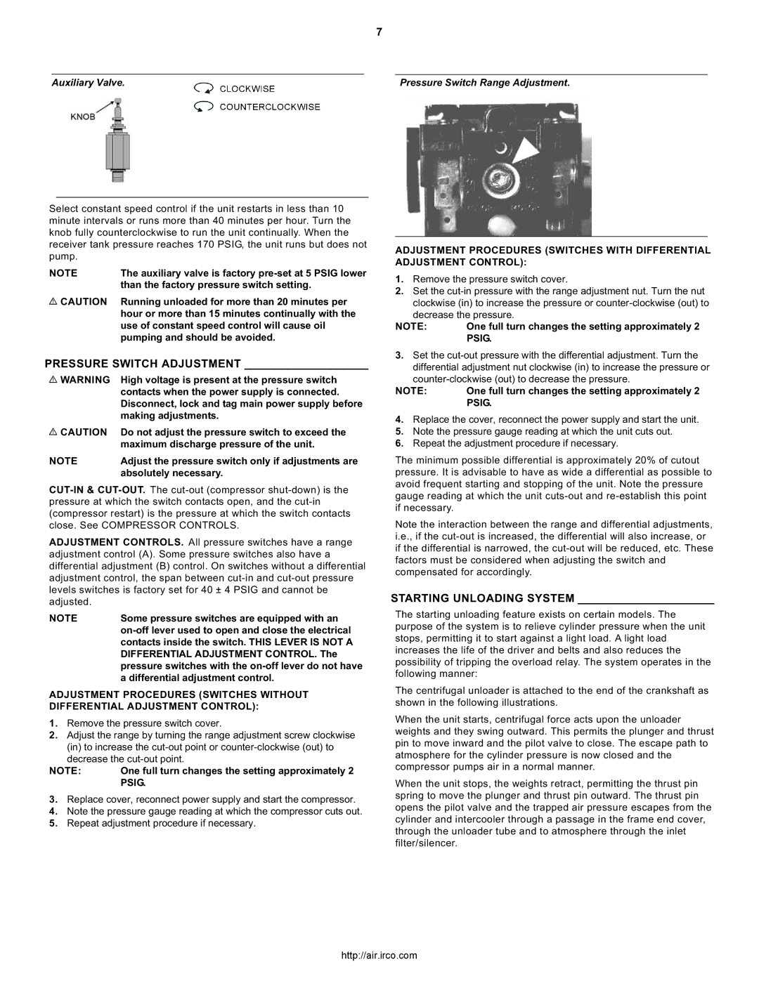
Auxiliary Valve.

Pressure Switch Range Adjustment.

Select constant speed control if the unit restarts in less than 10 minute intervals or runs more than 40 minutes per hour. Turn the knob fully counterclockwise to run the unit continually. When the receiver tank pressure reaches 170 PSIG, the unit runs but does not pump.

NOTE

The auxiliary valve is factory pre-set at 5 PSIG lower


than the factory pressure switch setting.

CAUTION

Running unloaded for more than 20 minutes per


hour or more than 15 minutes continually with the


use of constant speed control will cause oil


pumping and should be avoided.

PRESSURE SWITCH ADJUSTMENT ____________________

WARNING

High voltage is present at the pressure switch


contacts when the power supply is connected.


Disconnect, lock and tag main power supply before


making adjustments.

CAUTION

Do not adjust the pressure switch to exceed the


maximum discharge pressure of the unit.

NOTE

Adjust the pressure switch only if adjustments are


absolutely necessary.

CUT-IN & CUT-OUT.The cut-out (compressor shut-down) is the pressure at which the switch contacts open, and the cut-in (compressor restart) is the pressure at which the switch contacts close. See COMPRESSOR CONTROLS.

ADJUSTMENT CONTROLS. All pressure switches have a range adjustment control (A). Some pressure switches also have a differential adjustment (B) control. On switches without a differential adjustment control, the span between cut-in and cut-out pressure levels switches is factory set for 40 ± 4 PSIG and cannot be adjusted.

NOTE

Some pressure switches are equipped with an


on-off lever used to open and close the electrical


contacts inside the switch. THIS LEVER IS NOT A


DIFFERENTIAL ADJUSTMENT CONTROL. The


pressure switches with the on-off lever do not have


a differential adjustment control.

ADJUSTMENT PROCEDURES (SWITCHES WITHOUT DIFFERENTIAL ADJUSTMENT CONTROL):

1.Remove the pressure switch cover.

2.Adjust the range by turning the range adjustment screw clockwise (in) to increase the cut-out point or counter-clockwise (out) to decrease the cut-out point.

NOTE:

One full turn changes the setting approximately 2


PSIG.

3.Replace cover, reconnect power supply and start the compressor.

4.Note the pressure gauge reading at which the compressor cuts out.

5.Repeat adjustment procedure if necessary.

ADJUSTMENT PROCEDURES (SWITCHES WITH DIFFERENTIAL ADJUSTMENT CONTROL):

1.Remove the pressure switch cover.

2.Set the cut-in pressure with the range adjustment nut. Turn the nut

clockwise (in) to increase the pressure or counter-clockwise (out) to decrease the pressure.

NOTE: One full turn changes the setting approximately 2 PSIG.

3.Set the cut-out pressure with the differential adjustment. Turn the

differential adjustment nut clockwise (in) to increase the pressure or counter-clockwise (out) to decrease the pressure.

NOTE: One full turn changes the setting approximately 2 PSIG.

4.Replace the cover, reconnect the power supply and start the unit.

5.Note the pressure gauge reading at which the unit cuts out.

6.Repeat the adjustment procedure if necessary.

The minimum possible differential is approximately 20% of cutout pressure. It is advisable to have as wide a differential as possible to avoid frequent starting and stopping of the unit. Note the pressure gauge reading at which the unit cuts-out and re-establish this point if necessary.

Note the interaction between the range and differential adjustments, i.e., if the cut-out is increased, the differential will also increase, or if the differential is narrowed, the cut-out will be reduced, etc. These factors must be considered when adjusting the switch and compensated for accordingly.

STARTING UNLOADING SYSTEM ______________________

The starting unloading feature exists on certain models. The purpose of the system is to relieve cylinder pressure when the unit stops, permitting it to start against a light load. A light load increases the life of the driver and belts and also reduces the possibility of tripping the overload relay. The system operates in the following manner:

The centrifugal unloader is attached to the end of the crankshaft as shown in the following illustrations.

When the unit starts, centrifugal force acts upon the unloader weights and they swing outward. This permits the plunger and thrust pin to move inward and the pilot valve to close. The escape path to atmosphere for the cylinder pressure is now closed and the compressor pumps air in a normal manner.

When the unit stops, the weights retract, permitting the thrust pin spring to move the plunger and thrust pin outward. The thrust pin opens the pilot valve and the trapped air pressure escapes from the cylinder and intercooler through a passage in the frame end cover, through the unloader tube and to atmosphere through the inlet filter/silencer.

http://air.irco.com

Page 7
Image 7
Ingersoll-Rand 7100, 3000, 2475, 2340, 15T, 2545 Pressure Switch Adjustment, Starting Unloading System, Auxiliary Valve, Psig

7100, 2475, 2340, 3000, 2545 specifications

Ingersoll-Rand is a recognized leader in the field of industrial tools and compressed air solutions, and among their notable product offerings are the air compressor models: 15T, 2545, 3000, 2340, and 2475. These models are engineered to meet various industrial needs, providing reliable performance with enhanced efficiency and durability.

The Ingersoll-Rand 15T is a compact yet powerful rotary screw air compressor designed for small- to medium-sized operations. It features a robust build along with a user-friendly interface, allowing operators to easily adjust settings. Known for its low noise levels and energy efficiency, the 15T is ideal for applications requiring consistent air supply in a quiet environment.

The 2545 model is a workhorse in the family, recognized for its high output and extensive capabilities. It leverages advanced rotary screw technology, which provides continuous air flow while minimizing energy consumption. With its high-efficiency air end, the 2545 significantly reduces operating costs, making it suitable for heavy-duty tasks in demanding environments.

The Ingersoll-Rand 3000 is a portable solution that combines mobility with powerful performance. Featuring a rugged design, the 3000 is well-suited for construction sites and outdoor applications. It comes equipped with a reliable cooling system, enabling it to operate effectively in varying temperatures. Its compact design allows it to fit easily in tight spaces while providing ample air power.

The 2340 model emphasizes versatility and reliability, often used in automotive, manufacturing, and energy industries. It offers advanced features such as built-in control systems and service indicators, making maintenance simpler. This model is highly regarded for its reliability, which minimizes downtime and maximizes productivity.

Lastly, the Ingersoll-Rand 2475 is a robust compressor characterized by high flow rates and exceptional durability. It is engineered for large-scale applications, supporting heavy machinery and pneumatic tools. It incorporates sophisticated technology that ensures low noise emissions and energy-efficient operation, catering to workplaces that prioritize eco-friendliness.

Incorporating features like variable-speed drives, advanced cooling systems, and comprehensive monitoring technology, all these models exemplify the commitment of Ingersoll-Rand to innovation and user-centric designs. Whether for small workshops or large industrial operations, these compressors deliver unmatched performance and reliability, making them essential tools in various applications. Their consistent engineering excellence ensures that users can depend on Ingersoll-Rand products for their compressed air needs.