Controls & Connectors—Continued
Rear Panel
1 2 | 3 4 |
| VIDEO OUTPUT |
|
|
| ||
| COMPONENT 2 |
|
|
|
| |
Y | PB |
| PR |
|
|
|
| COMPONENT 1 |
|
| AUDIO OUTPUT | RS 232 | |
|
|
| DIGITAL |
| ||
Y | PB | PR | S VIDEO | OPTICAL | COAXIAL |
|
|
| |||||
AUDIO OUTPUT |
|
|
|
|
| |
| ANALOG |
| VIDEO |
|
|
|
| L |
| IN |
|
|
|
|
|
| IR |
|
|
|
| R |
| OUT | REMOTE |
|
|
|
|
|
| CONTROL |
|
|
5 6 7 89 J
DVD CHANGER
MODEL NO.
AC INLET
K |
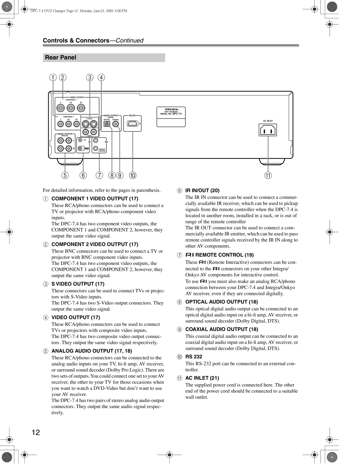
For detailed information, refer to the pages in parenthesis.
ACOMPONENT 1 VIDEO OUTPUT (17)
These RCA/phono connectors can be used to connect a TV or projector with RCA/phono component video inputs.
The
BCOMPONENT 2 VIDEO OUTPUT (17)
These BNC connectors can be used to connect a TV or projector with BNC component video inputs.
The
CS VIDEO OUTPUT (17)
These connectors can be used to connect TVs or projec- tors with
The
DVIDEO OUTPUT (17)
These RCA/phono connectors can be used to connect TVs or projectors with composite video inputs.
The
EANALOG AUDIO OUTPUT (17, 18)
These RCA/phono connectors can be connected to the analog audio inputs on your TV,
The
FIR IN/OUT (20)
The IR IN connector can be used to connect a commer- cially available IR receiver, which can be used to pickup signals from the remote controller when the
The IR OUT connector can be used to connect a com- mercially available IR emitter, which can be used to pass remote controller signals received by the IR IN along to other AV components.
G
 REMOTE CONTROL (19)
These ![]()
![]() (Remote Interactive) connectors can be con-
(Remote Interactive) connectors can be con-
nected to the ![]()
![]() connectors on your other Integra/ Onkyo AV components for interactive control.
connectors on your other Integra/ Onkyo AV components for interactive control.
To use ![]()
![]() you must also make an analog RCA/phono connection between your
you must also make an analog RCA/phono connection between your
HOPTICAL AUDIO OUTPUT (18)
This optical digital audio output can be connected to an optical digital audio input on a
ICOAXIAL AUDIO OUTPUT (18)
This coaxial digital audio output can be connected to an coaxial digital audio input on a
JRS 232
This
KAC INLET (21)
The supplied power cord is connected here. The other end of the power cord should be connected to a suitable wall outlet.
12