DTR-8.2 specifications
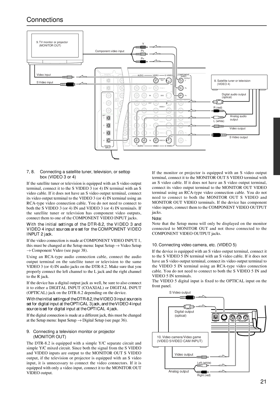
The Integra DTR-8.2 is a high-performance A/V receiver that stands at the crossroads of functionality and sophistication, designed for the discerning audiophile and home theater enthusiast. This powerful receiver offers a robust suite of features and technologies that enhance the listening experience while seamlessly integrating into modern home entertainment setups.One of the standout features of the DTR-8.2 is its advanced power amplification. With a 9.2 channel configuration, it delivers a potent output, ensuring that every movie, concert, or gaming session is filled with immersive sound. The receiver is equipped with high-current amplification and features a robust power supply, which works in tandem to deliver clear, dynamic audio even at high volumes.
In terms of audio processing, the DTR-8.2 supports Dolby Atmos and DTS:X, two cutting-edge technologies that create a three-dimensional sound environment. This immersive audio experience is further enhanced by its support for various high-resolution audio formats, allowing music lovers to enjoy studio-quality playback of their favorite tracks.
The receiver also features integrated network capabilities, with built-in Wi-Fi and Ethernet connectivity. This allows users to access a wide range of streaming services, including popular platforms like Spotify, Amazon Music, and Tidal. With Chromecast built-in, AirPlay 2, and DTS Play-Fi support, streaming high-quality audio from various devices has never been easier.
Another noteworthy characteristic of the DTR-8.2 is its comprehensive HDMI connectivity. It includes multiple HDMI inputs and outputs that support 4K/60Hz video, HDR10, Dolby Vision, and HDCP 2.2, making it compatible with the latest video formats and ensuring that users are future-proofed against evolving technology.
The Integra DTR-8.2 also incorporates room calibration technology, namely MCACC (Multi-Channel Acoustic Calibration System), which fine-tunes audio output to suit the specific acoustics of the listening space. This ensures that every listener receives an optimal sound experience, regardless of the room's layout.
In conclusion, the Integra DTR-8.2 is a multifaceted A/V receiver that combines cutting-edge audio and video technologies with user-friendly features. Its combination of power, versatility, and high-tech integrations makes it an ideal centerpiece for any home theater system, catering to those who seek both quality and performance in their audio-visual experiences.

