Optional Tuner Boards—Continued
Installing a Tuner Board
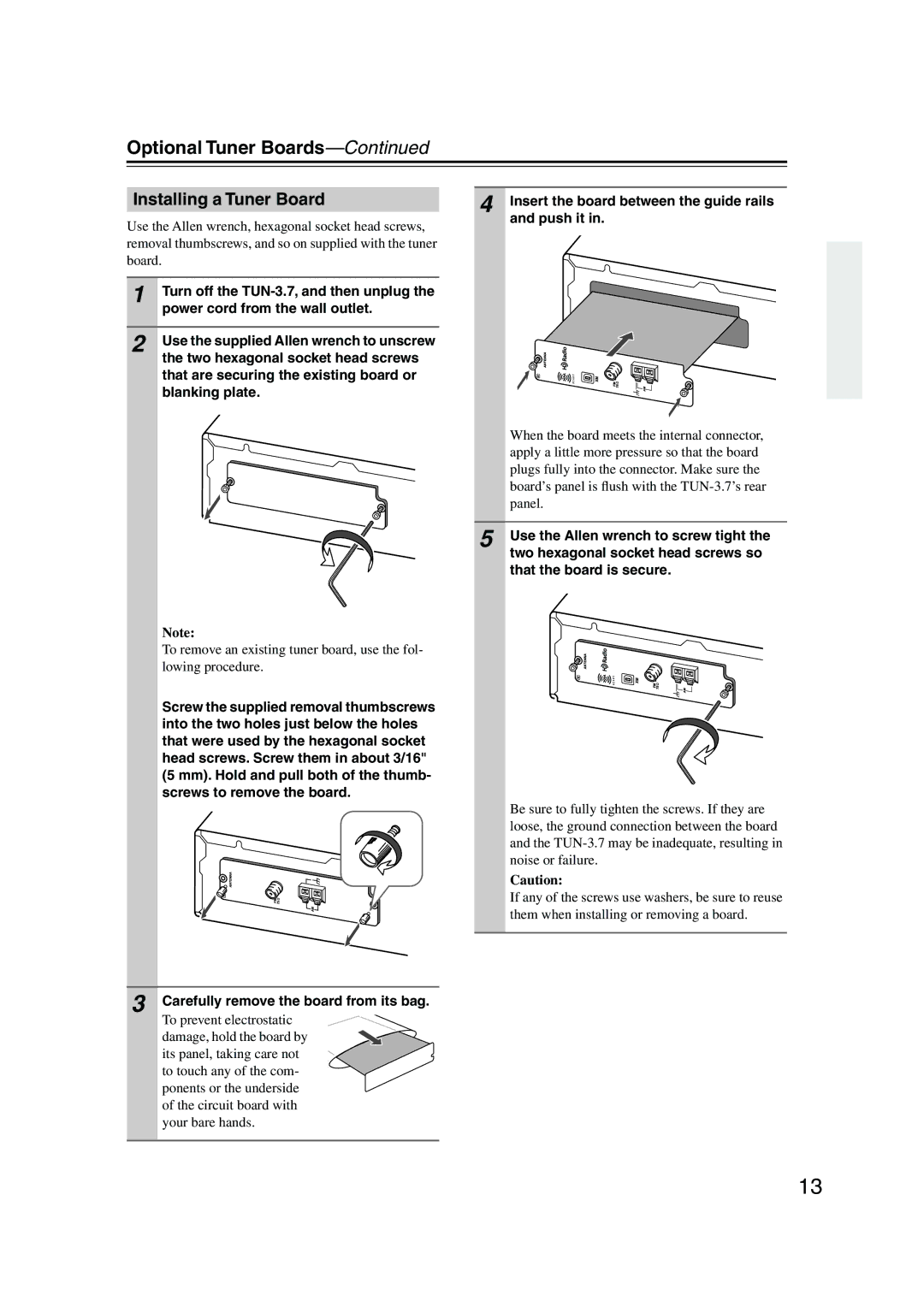
Use the Allen wrench, hexagonal socket head screws, removal thumbscrews, and so on supplied with the tuner board.
1 | Turn off the |
| power cord from the wall outlet. |
|
|
2 | Use the supplied Allen wrench to unscrew |
the two hexagonal socket head screws that are securing the existing board or blanking plate.
Note:
To remove an existing tuner board, use the fol- lowing procedure.
Screw the supplied removal thumbscrews into the two holes just below the holes that were used by the hexagonal socket head screws. Screw them in about 3/16" (5 mm). Hold and pull both of the thumb- screws to remove the board.
75
3 Carefully remove the board from its bag.
To prevent electrostatic damage, hold the board by its panel, taking care not to touch any of the com- ponents or the underside of the circuit board with your bare hands.
4 Insert the board between the guide rails and push it in.
When the board meets the internal connector, apply a little more pressure so that the board plugs fully into the connector. Make sure the board’s panel is flush with the
5 Use the Allen wrench to screw tight the two hexagonal socket head screws so that the board is secure.
Be sure to fully tighten the screws. If they are loose, the ground connection between the board and the
Caution:
If any of the screws use washers, be sure to reuse them when installing or removing a board.
13
