Manuals
/
Intel
/
Computer Equipment
/
Computer Hardware
Intel
AW8D
user manual
Motherboard Layout
Models:
AW8D
1
7
80
80
Download
80 pages
61.63 Kb
4
5
6
7
8
9
10
11
Page 7
Image 7
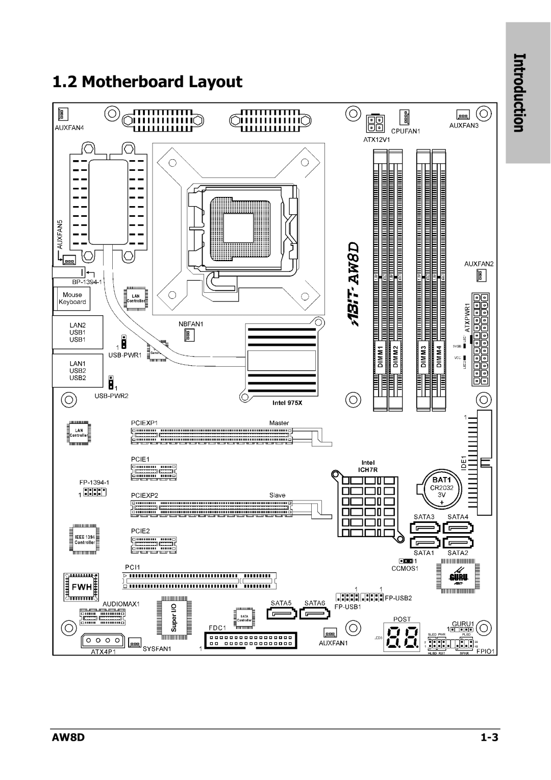
1.2 Motherboard Layout
Introduction
AW8D
1-3
Page 6
Page 8
Page 7
Image 7
Page 6
Page 8
Contents
Motherboard Intel Pentium Socket
AW8D
AW8D
Contents
Driver & Utility CD Support
Introduction
Features & Specifications
Expansion Slots
Motherboard Layout
AW8D
Choosing a Computer Chassis
Installing Motherboard
Short Open
Checking Jumper Settings
Cmos Memory Clearing Header and Backup Battery
AW8D
USB-PWR1
Wake-up Header
ATX Power Connectors
Connecting Chassis Components
Front Panel Switches & Indicators Headers
FAN Power Connectors
CPU Socket
Installing Hardware
AW8D
Hardware Setup
2 DDR2 Memory Slots
256MB 512MB
Floppy and IDE Disk Drive Connectors
PCI Express X16 Add-on Slots
AW8D
Serial ATA Connectors
AW8D
AudioMAX Connection Slot
MIC2 L
PCI Express X1 Add-on Slots
Hardware Setup PCI Add-on Slot
Additional USB 2.0 Port Headers
Connecting Optional Devices
Hardware
Additional IEEE1394 Port Header
Post Code Displayer
Onboard Status Display
Power Source Indicators
Connecting I/O Devices
Bios Setup
OC Guru
ΜGuru Utility
Bios Setup
Abit EQ
Temperature Monitoring
Voltage Monitoring
Fan Speed Monitoring
FanEQ Control
Bios Setup
AW8D
Standard Cmos Features
Back to Standard Cmos Features Setup Menu
AW8D
Advanced Bios Features
CPU Feature
Back to Advanced Bios Features Setup Menu
Bios Setup
Advanced Chipset Features
PCI Express Root Port Func
Back to Advanced Chipset Features Setup Menu
On-Chip IDE Device
Integrated Peripherals
Sata RAID ROM
Super-IO Device
On-Chip PCI Device
Onboard PCI Device
Power Management Setup
Bios Setup
AW8D
PnP/PCI Configurations
Save & Exit Setup
Load Fail-Safe Defaults
Load Optimized Defaults
Set Password
Driver & Utility CD Support
Intel Chipset Software Installation Utility
Intel Matrix Storage Technology Driver
Realtek Audio Driver
Realtek LAN Driver
Silicon Image 3132 Sata Driver
Silicon Image 3132 Sata RAID Driver
Abit µGuru Utility
USB 2.0 Driver
Award Post Code Definitions
Post Code Definitions
Early PCI Initialization
Auto
2 AC2005 Post Code Definitions
1 Q & a
Troubleshooting How to Get Technical Support?
AW8D
Appendix
Technical Support Form
RMA Center http//rma.abit-usa.com
Abit Contact Information
Abit Computer Corporation
Top
Page
Image
Contents