Installing and Replacing Desktop Board Components
Connecting to the USB 2.0 Headers
Before connecting to the USB 2.0 headers, observe the precautions in "Before You Begin" on page 31. See Figure 23, G on page 51 for the location of the three USB 2.0 headers. Table 11 shows the pin assignments for each USB 2.0 header. Each USB header can be used to connect two USB devices.
Table 11. USB 2.0 Header Signal Names
| USB Port A |
|
|
Pin | Signal Name |
1 | Power (+5 V) |
3 | D- |
5 | D+ |
7Ground
9Key
| USB Port B |
Pin | Signal Name |
2 | Power (+5 V) |
4 | D- |
6 | D+ |
8 | Ground |
10 | No Connection |
Note: USB ports may be assigned as needed.
![]() NOTE
NOTE
Computer systems that have an unshielded cable attached to a USB port might not meet FCC Class B requirements, even if no device or a
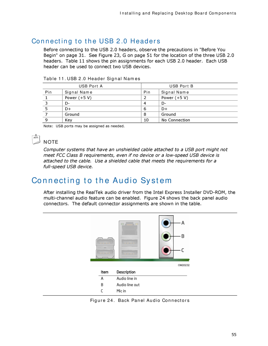
Connecting to the Audio System
After installing the RealTek audio driver from the Intel Express Installer
Item Description
AAudio line in
BAudio line out
CMic in
Figure 24. Back Panel Audio Connectors
55