Intel GA-N650SLI-DS4L B. Setting the SLI Configuration Jumpers, C. Connecting Two Graphics Cards

Models: GA-N650SLI-DS4L

1 100
Download 100 pages 30.59 Kb
Page 20
Image 20
B. Setting the SLI Configuration Jumpers:

B. Setting the SLI Configuration Jumpers:

The SLI configuration jumpers are set to Normal Mode operation by factory default, so the first step is to change the jumpers settings from Normal Mode to SLI Mode.

Step 1:

Move all the jumper caps from their default positions (pins 2-3) to pins 1-2, including the JP1 jumper.

Step 2:

The finished SLI jumper configurations are shown in the

photo to the left. All the jumper caps have been moved to pins 1-2.

C. Connecting Two Graphics Cards:

Step 1:

Observe the steps in
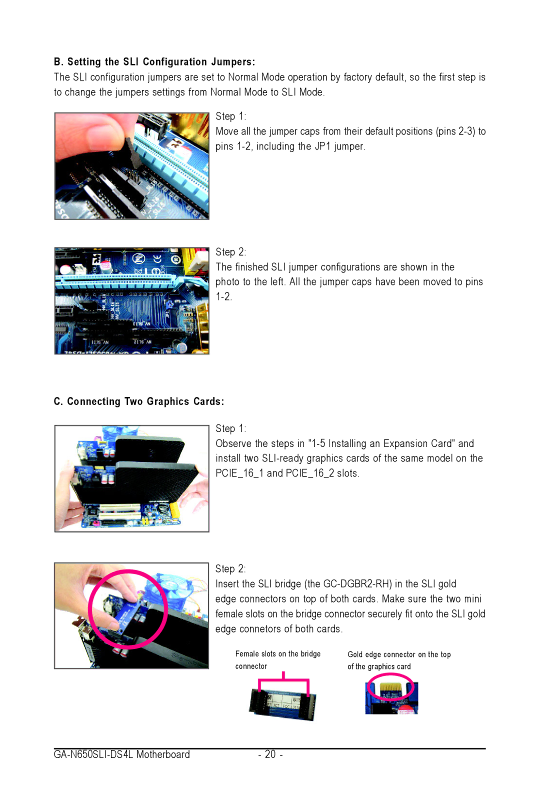
 "1-5 Installing an Expansion Card" and install two SLI-ready graphics cards of the same model on the PCIE_16_1 and PCIE_16_2 slots.

Step 2:

Insert the SLI bridge (the GC-DGBR2-RH) in the SLI gold edge connectors on top of both cards. Make sure the two mini female slots on the bridge connector securely fit onto the SLI gold edge connetors of both cards.

Female slots on the bridge

Gold edge connector on the top

connector

of the graphics card


GA-N650SLI-DS4L Motherboard

- 20 -

Page 20
Image 20
Intel GA-N650SLI-DS4L user manual B. Setting the SLI Configuration Jumpers, C. Connecting Two Graphics Cards, connector