OnChip IDE Function |
|
| ||||||
|
| CMOS Setup Utility – Copyright(C) | ||||||
|
|
|
|
| OnChip IDE Function |
|
| |
| OnChip IDE Channel0 |
|
|
|
|
| ||
| Enabled |
|
| |||||
| OnChip IDE Channel1 |
| Enabled |
|
| Item Help | ||
| Primary Master | PIO | Auto |
| ||||
| Primary Slave | PIO | Auto |
|
| |||
| Secondary Master PIO | Auto |
|
| ||||
|
|
| ||||||
| Secondary Slave | PIO | Auto |
|
| |||
| Primary Master | UDMA |
| Auto |
| Menu Level >> | ||
| Primary Slave | UDMA | Auto |
| ||||
| Secondary Master UDMA | Auto |
|
| ||||
| Secondary Slave | UDMA |
| Auto |
|
| ||
| IDE | Enabled |
|
| ||||
| IDE Prefetch Mode | Enabled |
|
| ||||
| IDE HDD Block Mode |
| Enabled |
|
| |||
| Delay For HDD (Secs) | 0 |
|
|
| |||
|
|
|
| |||||
|
| ↑↓→← Move Enter:Select | ||||||
|
| F5:Previous Values | F6:Optimized Defaults | F7:Standard Defaults | ||||
|
|
|
|
|
|
|
|
|
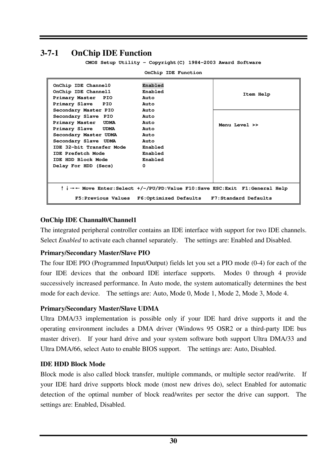
OnChip IDE Channal0/Channel1
The integrated peripheral controller contains an IDE interface with support for two IDE channels. Select Enabled to activate each channel separately. The settings are: Enabled and Disabled.
Primary/Secondary Master/Slave PIO
The four IDE PIO (Programmed Input/Output) fields let you set a PIO mode
Primary/Secondary Master/Slave UDMA
Ultra DMA/33 implementation is possible only if your IDE hard drive supports it and the operating environment includes a DMA driver (Windows 95 OSR2 or a
IDE HDD Block Mode
Block mode is also called block transfer, multiple commands, or multiple sector read/write. If your IDE hard drive supports block mode (most new drives do), select Enabled for automatic detection of the optimal number of block read/writes per sector the drive can support. The settings are: Enabled, Disabled.
30