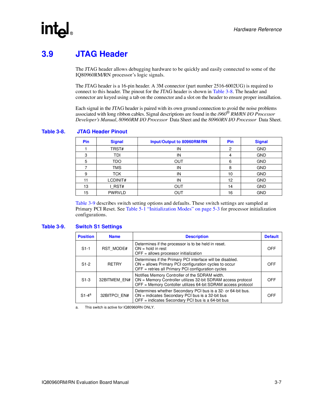
RN, IQ80960RM specifications
The Intel IQ80960RM and RN are part of the Intel i960 family of microprocessors, which were specifically designed for embedded applications in real-time computing environments. Introduced in the early 1990s, these processors were aimed at providing high-performance processing capabilities in industrial, telecommunications, and military systems.One of the key features of the IQ80960RM and RN is their ability to support a 32-bit architecture, delivering a significant performance advantage over 16-bit and earlier processors. This architecture enables the execution of complex algorithms and the management of large amounts of data, making these microprocessors suitable for demanding applications.
The i960 family is built around a superscalar architecture, allowing multiple instructions to be completed in a single clock cycle. This is achieved through advanced instruction pipelining, which significantly boosts throughput and overall computational speed. The IQ80960RM and RN also included features like branch prediction and out-of-order execution, enhancing efficiency and reducing latency in real-time applications.
Memory management capabilities are another strong point of the IQ80960RM and RN. They support both virtual and physical memory addressing, enabling sophisticated memory management strategies. Their integrated memory management unit (MMU) allows for easier and more effective memory allocation, critical for real-time operating systems that require precise timing and resource management.
Furthermore, these processors are designed with an extensive instruction set architecture (ISA), which supports a wide range of operations, including digital signal processing (DSP) tasks. This versatility allows them to be utilized in various applications, from automotive systems to robotics, where reliable performance is paramount.
The thermal performance and power efficiency of the IQ80960RM and RN has also been a notable characteristic. With operational capabilities across various temperature ranges, these chips are well-suited for harsh environments often found in industrial settings.
In terms of connectivity, the IQ80960 series supports multiple I/O interfaces and communication protocols, ensuring that they can integrate seamlessly with other components and systems. This flexibility enhances their usability in networked applications, particularly in embedded systems.
Overall, the Intel IQ80960RM and RN processors represent a significant step forward in embedded processor technology, characterized by their robust performance, advanced features, and ability to meet the stringent demands of real-time applications across various industries.
