12 HARDWARE INSTALLATION
2.4 Connector Description
2.4.1 Primary/Secondary IDE Connectors (Two
This motherboard supports two
If you intend to operate two IDE devices from the same channel, one device must be set to “Master” mode, the other to “Slave” mode. A Hard Disk Drive, CD ROM or other IDE device can have either setting depending on the device’s jumper. Please refer to the device’s manual for more information.
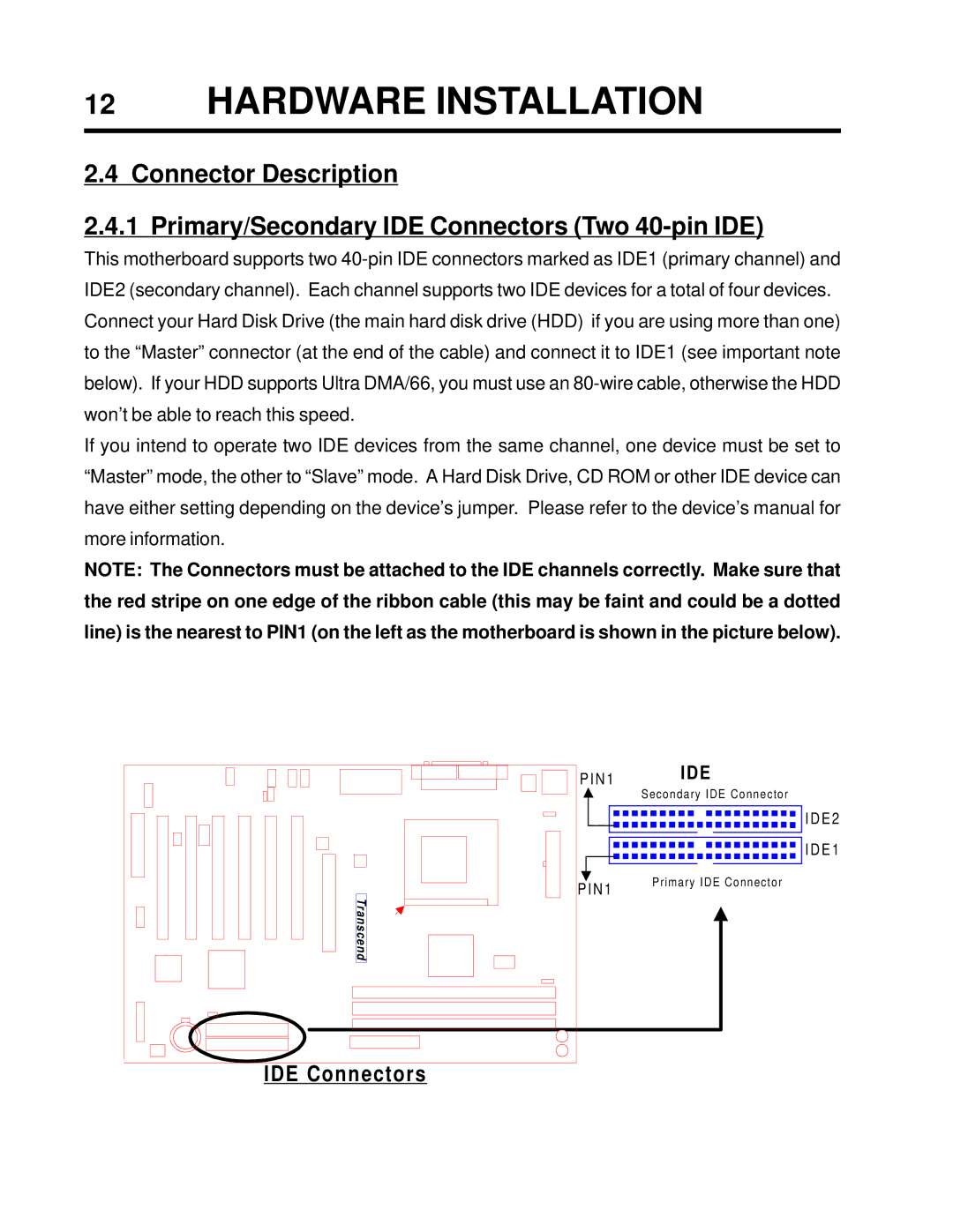
NOTE: The Connectors must be attached to the IDE channels correctly. Make sure that the red stripe on one edge of the ribbon cable (this may be faint and could be a dotted line) is the nearest to PIN1 (on the left as the motherboard is shown in the picture below).
P I N 1 | IDE |
| Secondary IDE Connector |
| I D E 2 |
| I D E 1 |
P I N 1 | Primary IDE Connector |
| |
Transcend |
|