SECTION
The joystick has proportional drive control, meaning that the further it is pushed from the upright (neutral) position, the faster the wheelchair moves. The maximum speed, however, is limited by the setting of the speed‐control knob.
To slow the wheelchair to a stop, simply release the joystick. The wheelchair has automatic speed and direction compensation to minimize corrections.
When first learning to drive, select a slow speed and try to drive the wheelchair as slowly as possible by pushing the joystick slightly forward. This exercise will help you learn to utilize the full potential of the proportional control and allow you to start and stop smoothly.
To drive the wheelchair, perform the following:
1.Adjust speed control knob to the appropriate setting.
2.Turn the power On. Refer to Turning the Power On/Off on page 35.
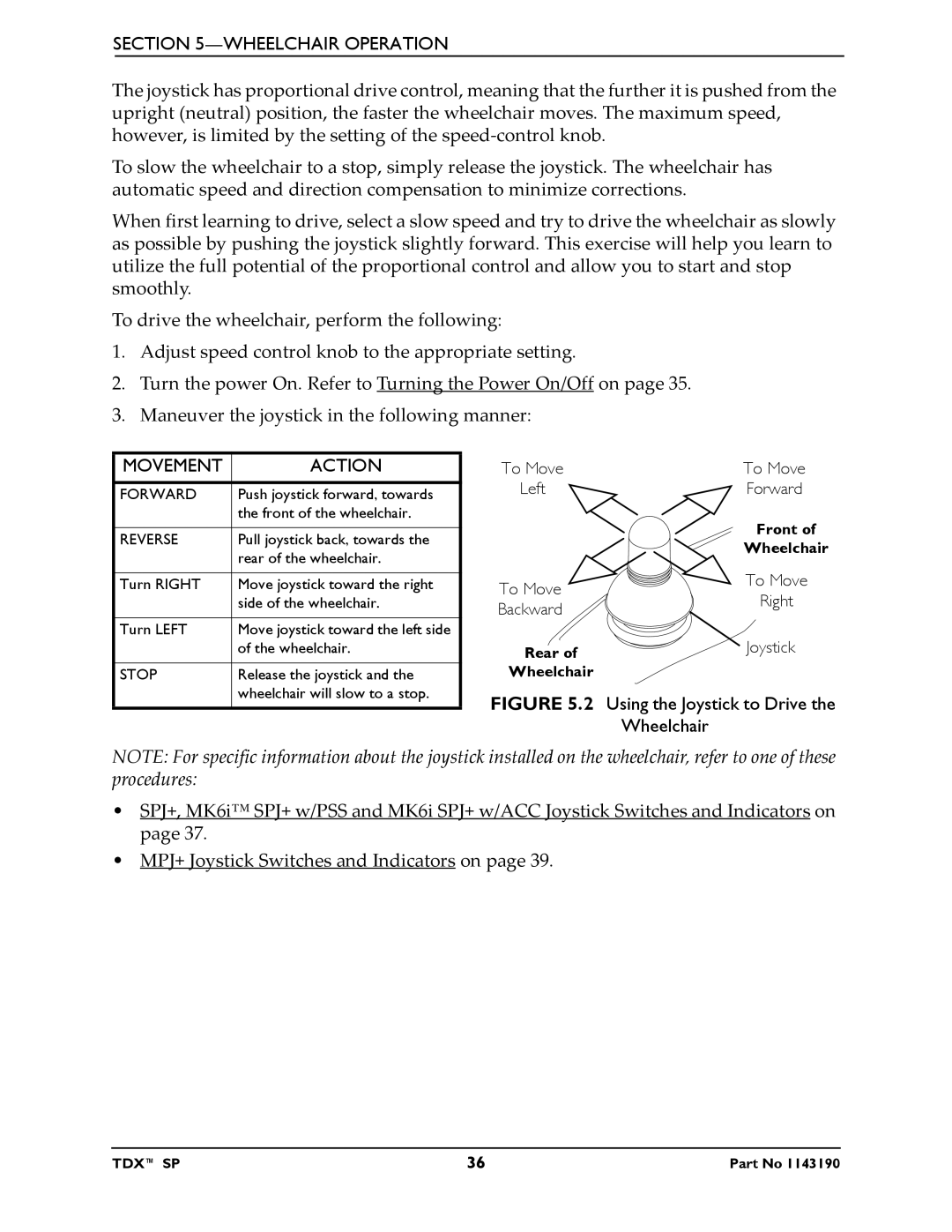
3.Maneuver the joystick in the following manner:
MOVEMENT | ACTION | To Move | To Move |
FORWARD | Push joystick forward, towards | Left | Forward |
|
| ||
| the front of the wheelchair. |
| Front of |
REVERSE | Pull joystick back, towards the |
| |
| Wheelchair | ||
| rear of the wheelchair. |
| |
|
|
| |
Turn RIGHT | Move joystick toward the right | To Move | To Move |
| side of the wheelchair. | Backward | Right |
|
|
| |
Turn LEFT | Move joystick toward the left side |
| Joystick |
| of the wheelchair. | Rear of | |
|
|
| |
STOP | Release the joystick and the | Wheelchair |
|
| wheelchair will slow to a stop. | FIGURE 5.2 Using the Joystick to Drive the | |
|
| ||
|
|
| Wheelchair |
NOTE: For specific information about the joystick installed on the wheelchair, refer to one of these procedures:
•SPJ+, MK6i™ SPJ+ w/PSS and MK6i SPJ+ w/ACC Joystick Switches and Indicators on page 37.
•MPJ+ Joystick Switches and Indicators on page 39.
TDX™ SP | 36 | Part No 1143190 |