SECTION 11—TRANSPORT READY PACKAGE (TRRO)
Positioning Belts
WARNING
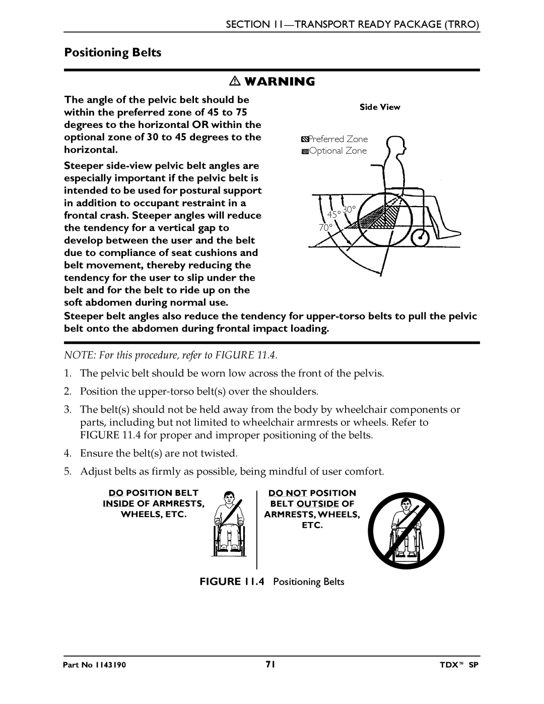
The angle of the pelvic belt should be within the preferred zone of 45 to 75 degrees to the horizontal OR within the optional zone of 30 to 45 degrees to the horizontal.
Steeper
Side View
Preferred Zone |
Optional Zone |
45° 30° |
70° |
Steeper belt angles also reduce the tendency for
NOTE: For this procedure, refer to FIGURE 11.4.
1.The pelvic belt should be worn low across the front of the pelvis.
2.Position the upper‐torso belt(s) over the shoulders.
3.The belt(s) should not be held away from the body by wheelchair components or parts, including but not limited to wheelchair armrests or wheels. Refer to FIGURE 11.4 for proper and improper positioning of the belts.
4.Ensure the belt(s) are not twisted.
5.Adjust belts as firmly as possible, being mindful of user comfort.
DO POSITION BELT
INSIDE OF ARMRESTS,
WHEELS, ETC.
DO NOT POSITION BELT OUTSIDE OF ARMRESTS, WHEELS, ETC.
FIGURE 11.4 Positioning Belts
Part No 1143190 | 71 | TDX™ SP |