SECTION
Connected Devices Screen
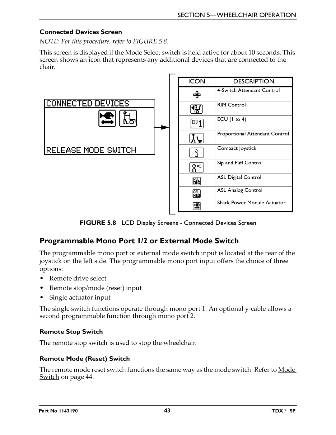
NOTE: For this procedure, refer to FIGURE 5.8.
This screen is displayed if the Mode Select switch is held active for about 10 seconds. This screen shows an icon that represents any additional devices that are connected to the chair.
ICON | DESCRIPTION |
| |
|
|
| RIM Control |
|
|
| ECU (1 to 4) |
|
|
| Proportional Attendant Control |
|
|
| Compact Joystick |
|
|
| Sip and Puff Control |
|
|
| ASL Digital Control |
|
|
| ASL Analog Control |
|
|
| Shark Power Module Actuator |
|
|
FIGURE 5.8 LCD Display Screens - Connected Devices Screen
Programmable Mono Port 1/2 or External Mode Switch
The programmable mono port or external mode switch input is located at the rear of the joystick on the left side. The programmable mono port input offers the choice of three options:
•Remote drive select
•Remote stop/mode (reset) input
•Single actuator input
The single switch functions operate through mono port 1. An optional y‐cable allows a second programmable function through mono port 2.
Remote Stop Switch
The remote stop switch is used to stop the wheelchair.
Remote Mode (Reset) Switch
The remote mode reset switch functions the same way as the mode switch. Refer to Mode Switch on page 44.
Part No 1143190 | 43 | TDX™ SP |
