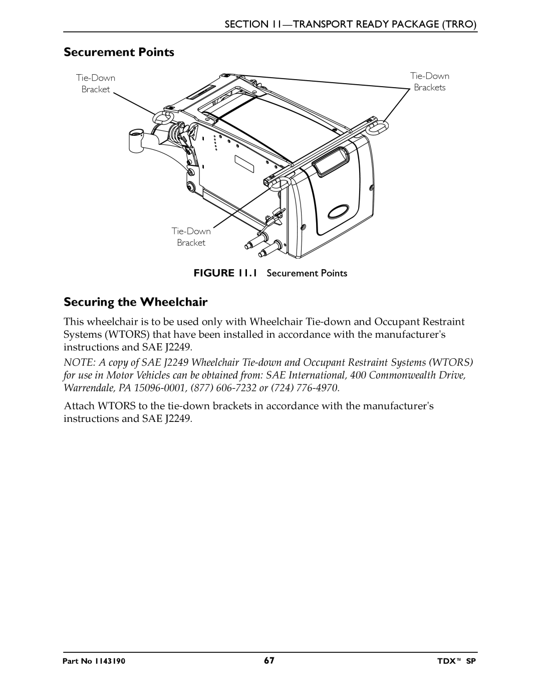
DEALER This manual MUST be given to the user of the wheelchair
Power Wheelchair Base
Owner’s Operator and Maintenance Manual
TDX SP
REFERENCE DOCUMENTS
REFERENCE DOCUMENTS
MANUAL
REFERENCE DOCUMENTS
TABLE OF CONTENTS
TABLE OF CONTENTS
SECTION 3-SAFETY/HANDLING OF WHEELCHAIRS
Using the Joystick to Drive the Wheelchair
TABLE OF CONTENTS
TABLE OF CONTENTS
SECTION 4-SAFETY INSPECTION/TROUBLESHOOTING
Installing the Front Shroud/Battery Retention Bracket and Rear Shroud
TABLE OF CONTENTS
TABLE OF CONTENTS
Removing the Front Shroud/Battery Retention Bracket and Rear Shroud
or Complete and mail the form on the next page
REGISTER YOUR PRODUCT
LIMITED WARRANTY
SECTION 11-TRANSPORT READY PACKAGE TRRO
here
PRODUCT REGISTRATION FORM
Cut Along Line
Fold
Invacare Product Registration Form Please Seal with
Fold here Cut Along Line Fold here
Tape Before Mailing
SPECIAL NOTES
TRRO AND TRBKTS WARNINGS
Weight Capacity Label located here
LABEL LOCATIONS
All Wheelchairs
Wheelchairs with 22NF Batteries
USE this
Wheelchairs with GP24 Batteries
battery
LABEL LOCATIONS
NOTE Also on opposite side
Wheelchairs with TRRO
Wheelchairs without TRRO
LABEL LOCATIONS
NOTE All dimensions are ±.50 inches unless otherwise indicated
TYPICAL PRODUCT PARAMETERS
SECTION 1-GENERAL GUIDELINES
Repair or Service Information
Operation Information
Wheelchairs with TRRO or TRBKTS Only
Tire Pressure
Charging Batteries DANGER
Electrical
Batteries
Grounding Instructions
Weight Limitation
Weight Training
Rain Test
SECTION 2-EMI INFORMATION
Powered Wheelchair Electromagnetic Interference EMI
Stability and Balance
SECTION 3-SAFETY/HANDLING OF WHEELCHAIRS
NOTE For this procedure, refer to FIGURE
Coping with Everyday Obstacles
Reaching, Leaning and Bending - Forward
A Note to Wheelchair Assistants
NOTE For this procedure, refer to
Pinch point may occur when rotating the footboard assembly Detail “C”
Reaching, Bending - Backward
Pinch Points
NOTE For this procedure, refer to
WARNING ESCALATORS
Stairways
NOTE For this procedure, refer to FIGURE
Transferring To and From Other Seats
Safety Inspection Checklists
SECTION 4-SAFETY INSPECTION/ TROUBLESHOOTING
Inspect/Adjust Monthly
Inspect/Adjust Weekly
SECTION 4-SAFETY INSPECTION/TROUBLESHOOTING
Inspect/Adjust Every 2 Years
Troubleshooting - Mechanical
Inspect/Adjust Periodically
Inspect/Adjust Every 18 Months
SPJ+, SPJ+ w/PSS or SPJ+ w/ACC Joysticks
Troubleshooting - Electrical
SOLUTIONS
SECTION 4-SAFETY INSPECTION/TROUBLESHOOTING
POSSIBLE SOLUTION
SYMPTOM
PROBABLE CAUSE
SECTION 4-SAFETY INSPECTION/TROUBLESHOOTING
SYMPTOM
SOLUTIONS
SECTION 4-SAFETY INSPECTION/TROUBLESHOOTING
Checking Battery Charge Level
DON’T
NOTE For this procedure, refer to FIGURE 5.2 on page
SECTION 5-WHEELCHAIR OPERATION
Operating the Wheelchair
NOTE For this procedure, refer to FIGURE
To drive the wheelchair, perform the following
NOTE For the following information, refer to FIGURE
NOTE The mode button is only present on SPJ+ w/ACC joystick
On/Off Button
Speedometer
Charger/Programming Input
Service Indicator
Speed Control Buttons
Joystick
Information Gauge Display
MPJ+ Joystick Switches and Indicators
Drive Select Toggle Switch
NOTE For this procedure, refer to FIGURE 5.4 on page
Charger/Programming Input
Switch
Speed Control
Joystick
NOTE For this information, refer to FIGURE 5.6 on page
NOTE For this procedure, refer to
Splash Screen
Main Screen
message, status icon and battery indicator are
NOTE For this procedure, refer to
This screen is shown when the operator
issues a drive command and the Drive Icon
Remote Mode Reset Switch
Programmable Mono Port 1/2 or External Mode Switch
NOTE For this procedure, refer to FIGURE
Remote Stop Switch
Memory Card Slot
Remote On/Off Switch
Mode Switch
NOTE For this procedure, refer to FIGURE 5.4 on page
not shown
Repositioning Joystick
NOTE For this procedure, refer to FIGURE
Van Seats
NOTE The joystick connector is located at the rear of the seat frame
Disconnecting/Connecting the Joysticks
NOTE For this procedure, refer to
NOTE For this procedure, refer to FIGURE 5.11 on page
MPJ+ Joysticks
NOTE For this procedure, refer to FIGURE
Disengaging/Engaging Motor Lock Levers
SECTION 6-MOTOR LOCKS
NOTE For this procedure, refer to FIGURE
Disengaging/Engaging the Wheel locks
SECTION 7-WHEEL LOCKS
NOTE For this procedure, refer to FIGURE
Removing/Installing the Footboard
SECTION 8-FOOTBOARD ASSEMBLY
NOTE For this procedure, refer to FIGURE 8.1 on page
Washers
Adjusting the Footboard Angle
NOTE For this procedure, refer to FIGURE
Footboard Support
SECTION 9-FORKS
Adjusting Forks
NOTE For this procedure, refer to FIGURE
SECTION 10-BATTERIES
1. Position battery on ground/flat surface as shown below
Using the Proper Batteries
2. Visually inspect the battery to ensure proper polarity
Wire Cutter
Replacing Batteries
NOTE For this procedure, refer to FIGURE 10.1 on page
NOTE The following tools are required to perform this procedure
RED Battery
BLACK Battery
Battery Wiring Harness
Battery Cable
NOTE For this procedure, refer to FIGURE 10.2 on page
Cleaning Battery Terminals
Removing/Installing the Batteries From/Into the Wheelchair
Removing the Front Shroud/Battery Retention Bracket and Rear Shroud
Front Shroud
NOTE Battery retention bracket for two 22nf batteries shown
Battery Retention Bracket
Controller
NOTE 22NF Batteries
NOTE For this procedure, refer to FIGURE 10.3 on page
NOTE Battery tray
NOTE For this procedure, refer to FIGURE 10.3 and FIGURE 10.4 on page
NOTE For this procedure, refer to FIGURE 10.2 on page
Installing the Front Shroud/Battery Retention Bracket and Rear Shroud
NOTE 22NF Batteries shown
SPJ+, SPJ+ w/PSS and SPJ+ w/ACC Joysticks
When to Charge Batteries
NOTE For this procedure, refer to FIGURE
NOTE For this procedure, refer to FIGURE 10.6 on page
Description and Use of Battery Chargers
Charging Batteries
NOTE For this procedure, refer to FIGURE 10.7 on page
Required Items
SECTION 11-TRANSPORT READY PACKAGE TRRO
Compliance Information
About Transport Ready Packages
Specifications
Securing the Wheelchair to the Vehicle
Positioning the Wheelchair in the Vehicle
Securing the Wheelchair
Securement Points
FIGURE 11.1 Securement Points
NOTE For this procedure, refer to FIGURE 11.2 on page
Securing the Occupant
Wheelchair-Anchored Belts
Male End
SECTION 11-TRANSPORT READY PACKAGE TRRO
FIGURE 11.2 Wheelchair-Anchored Belts
Pelvic Belt Pin Used to secure the vehicle anchored upper-torso belt
RATING
NOTE For this procedure, refer to FIGURE
Vehicle-Anchored Belts
Seating System
1. The pelvic belt should be worn low across the front of the pelvis
NOTE For this procedure, refer to FIGURE
5. Adjust belts as firmly as possible, being mindful of user comfort
Positioning Belts
LIMITED WARRANTY