SECTION 6—MOTOR LOCKS
SECTION 6—MOTOR LOCKS
WARNING
After ANY adjustments, repair or service and before use, make sure that all attaching hardware is tightened securely - otherwise injury or damage may result.
CAUTION
As with any vehicle, the wheels and tires should be checked periodically for cracks and wear, and should be replaced.
Disengaging/Engaging Motor Lock Levers
WARNING
DO NOT engage or disengage motor locks until the power is in the OFF position.
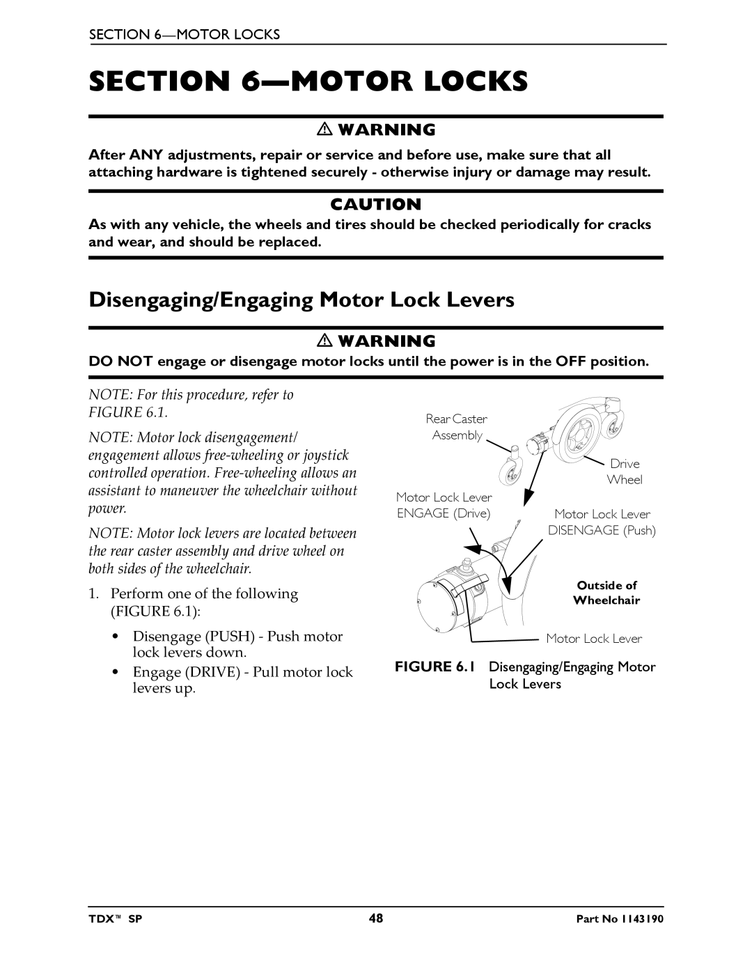
NOTE: For this procedure, refer to FIGURE 6.1.
NOTE: Motor lock disengagement/ engagement allows free‐wheeling or joystick controlled operation. Free‐wheeling allows an assistant to maneuver the wheelchair without power.
NOTE: Motor lock levers are located between the rear caster assembly and drive wheel on both sides of the wheelchair.
1.Perform one of the following (FIGURE 6.1):
•Disengage (PUSH) ‐ Push motor lock levers down.
•Engage (DRIVE) ‐ Pull motor lock levers up.
Rear Caster
Assembly
| Drive |
| Wheel |
Motor Lock Lever |
|
ENGAGE (Drive) | Motor Lock Lever |
| DISENGAGE (Push) |
| Outside of |
| Wheelchair |
| Motor Lock Lever |
FIGURE 6.1 Disengaging/Engaging Motor
Lock Levers
TDX™ SP | 48 | Part No 1143190 |