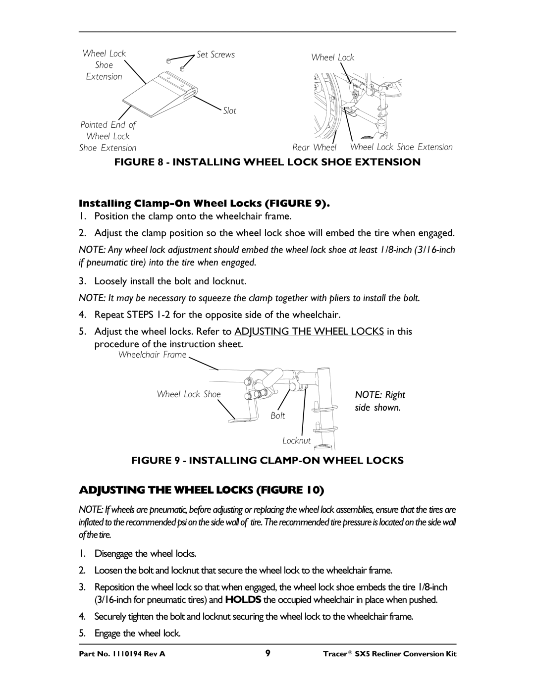
Wheel Lock | Set Screws | Wheel Lock |
Shoe |
| |
|
| |
Extension |
|
|
| Slot |
|
Pointed End of |
|
|
Wheel Lock |
| Rear Wheel Wheel Lock Shoe Extension |
Shoe Extension |
|
FIGURE 8 - INSTALLING WHEEL LOCK SHOE EXTENSION
Installing Clamp-On Wheel Locks (FIGURE 9).
1.Position the clamp onto the wheelchair frame.
2.Adjust the clamp position so the wheel lock shoe will embed the tire when engaged.
NOTE: Any wheel lock adjustment should embed the wheel lock shoe at least
3. Loosely install the bolt and locknut.
NOTE: It may be necessary to squeeze the clamp together with pliers to install the bolt.
4.Repeat STEPS
5.Adjust the wheel locks. Refer to ADJUSTING THE WHEEL LOCKS in this
procedure of the instruction sheet.
Wheelchair Frame
Wheel Lock Shoe | NOTE: Right |
| side shown. |
| Bolt |
Locknut
FIGURE 9 - INSTALLING CLAMP-ON WHEEL LOCKS
ADJUSTING THE WHEEL LOCKS (FIGURE 10)
NOTE: If wheels are pneumatic, before adjusting or replacing the wheel lock assemblies, ensure that the tires are inflated to the recommended psi on the side wall of tire. The recommended tire pressure is located on the side wall of the tire.
1.Disengage the wheel locks.
2.Loosen the bolt and locknut that secure the wheel lock to the wheelchair frame.
3.Reposition the wheel lock so that when engaged, the wheel lock shoe embeds the tire
4.Securely tighten the bolt and locknut securing the wheel lock to the wheelchair frame.
5.Engage the wheel lock.
Part No. 1110194 Rev A | 9 | Tracer® SX5 Recliner Conversion Kit |