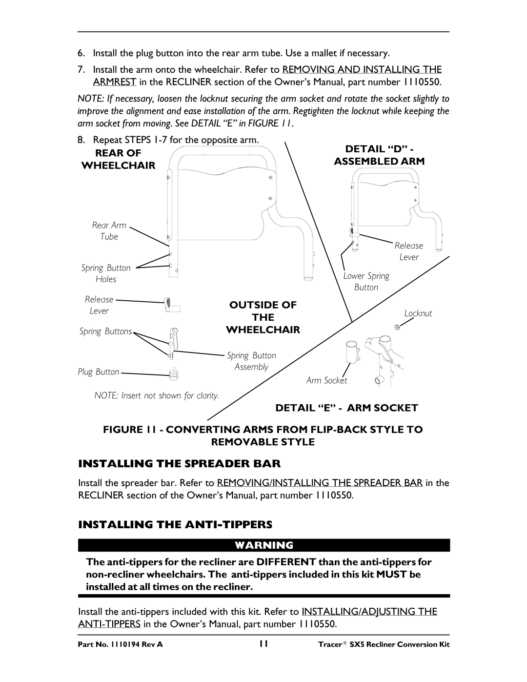
6.Install the plug button into the rear arm tube. Use a mallet if necessary.
7.Install the arm onto the wheelchair. Refer to REMOVING AND INSTALLING THE ARMREST in the RECLINER section of the Owner’s Manual, part number 1110550.
NOTE: If necessary, loosen the locknut securing the arm socket and rotate the socket slightly to improve the alignment and ease installation of the arm. Regtighten the locknut while keeping the arm socket from moving. See DETAIL “E” in FIGURE 11.
8. Repeat STEPS | DETAIL “D” - | |
REAR OF | ||
ASSEMBLED ARM | ||
WHEELCHAIR | ||
|
Rear Arm
Tube
Spring Button
Holes
Release
Lever
Spring Buttons
Plug Button
NOTE: Insert not shown for clarity.
Release
Lever
Lower Spring
Button
OUTSIDE OF
THELocknut
WHEELCHAIR
Spring Button
Assembly
Arm Socket
DETAIL “E” - ARM SOCKET
FIGURE 11 - CONVERTING ARMS FROM FLIP-BACK STYLE TO
REMOVABLE STYLE
INSTALLING THE SPREADER BAR
Install the spreader bar. Refer to REMOVING/INSTALLING THE SPREADER BAR in the RECLINER section of the Owner’s Manual, part number 1110550.
INSTALLING THE ANTI-TIPPERS
WARNING
The
Install the
Part No. 1110194 Rev A | 11 | Tracer® SX5 Recliner Conversion Kit |
