Compound Rest
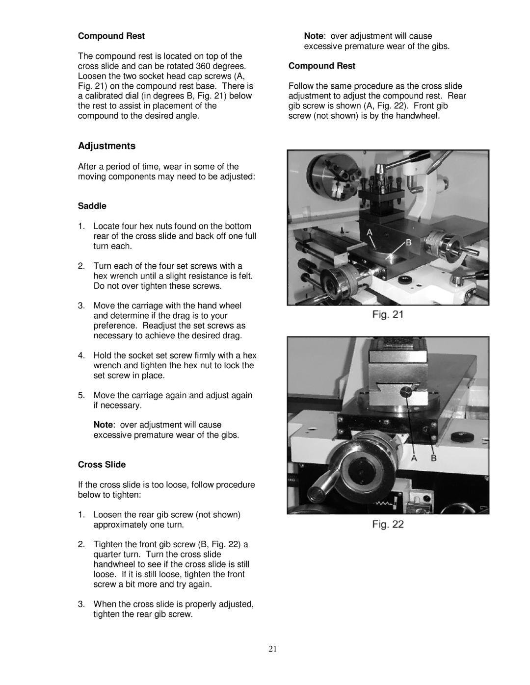
The compound rest is located on top of the cross slide and can be rotated 360 degrees. Loosen the two socket head cap screws (A, Fig. 21) on the compound rest base. There is a calibrated dial (in degrees B, Fig. 21) below the rest to assist in placement of the compound to the desired angle.
Adjustments
After a period of time, wear in some of the moving components may need to be adjusted:
Saddle
1.Locate four hex nuts found on the bottom rear of the cross slide and back off one full turn each.
2.Turn each of the four set screws with a hex wrench until a slight resistance is felt. Do not over tighten these screws.
3.Move the carriage with the hand wheel and determine if the drag is to your preference. Readjust the set screws as necessary to achieve the desired drag.
4.Hold the socket set screw firmly with a hex wrench and tighten the hex nut to lock the set screw in place.
5.Move the carriage again and adjust again if necessary.
Note: over adjustment will cause excessive premature wear of the gibs.
Cross Slide
If the cross slide is too loose, follow procedure below to tighten:
1.Loosen the rear gib screw (not shown) approximately one turn.
2.Tighten the front gib screw (B, Fig. 22) a quarter turn. Turn the cross slide handwheel to see if the cross slide is still loose. If it is still loose, tighten the front screw a bit more and try again.
3.When the cross slide is properly adjusted, tighten the rear gib screw.
Note: over adjustment will cause excessive premature wear of the gibs.
Compound Rest
Follow the same procedure as the cross slide adjustment to adjust the compound rest. Rear gib screw is shown (A, Fig. 22). Front gib screw (not shown) is by the handwheel.
21