15.Tool Post Clamping Lever (J, Fig. 14) - located on top of the tool post. Rotate
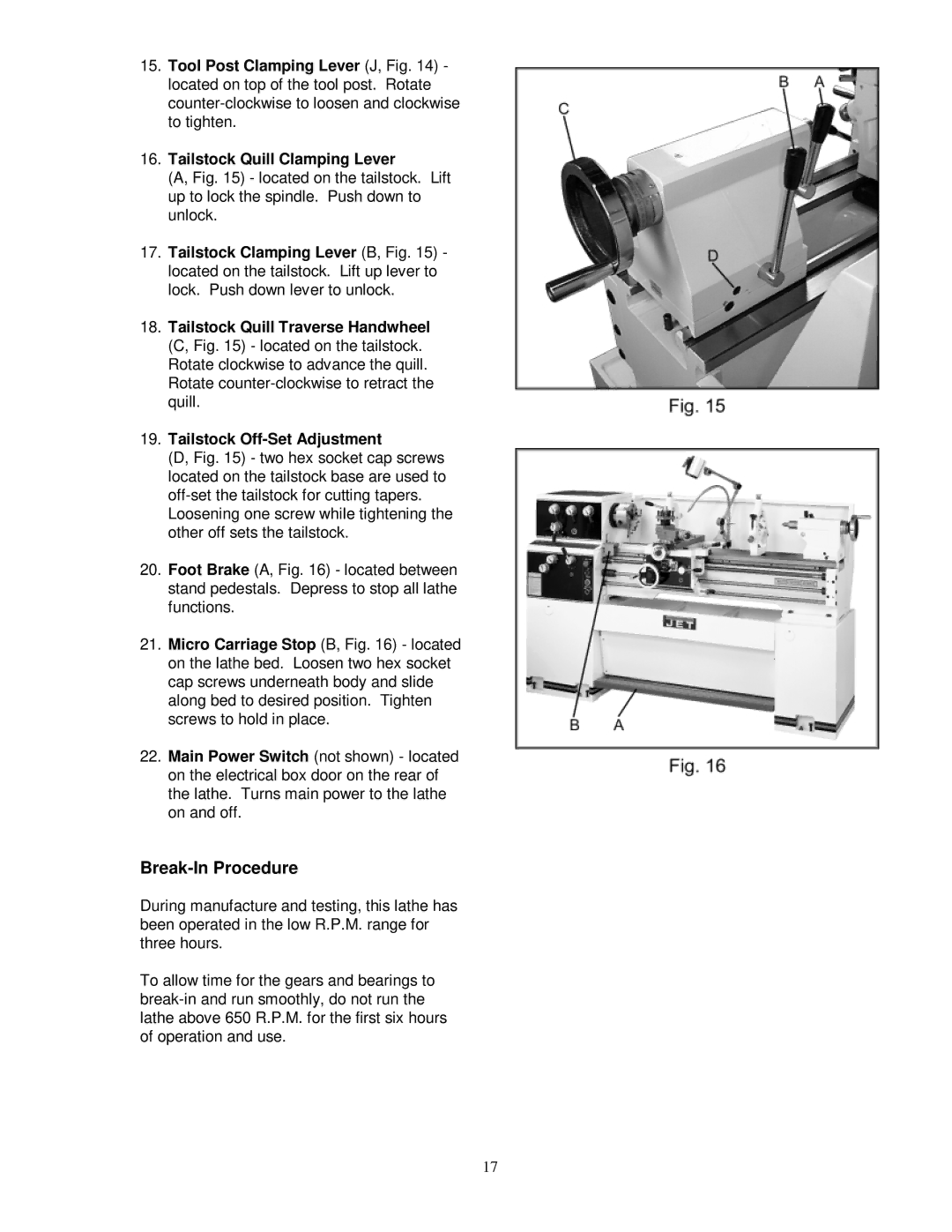
16.Tailstock Quill Clamping Lever
(A, Fig. 15) - located on the tailstock. Lift up to lock the spindle. Push down to unlock.
17.Tailstock Clamping Lever (B, Fig. 15) - located on the tailstock. Lift up lever to lock. Push down lever to unlock.
18.Tailstock Quill Traverse Handwheel (C, Fig. 15) - located on the tailstock. Rotate clockwise to advance the quill. Rotate
19.Tailstock
(D, Fig. 15) - two hex socket cap screws located on the tailstock base are used to off-set the tailstock for cutting tapers.
Loosening one screw while tightening the other off sets the tailstock.
20.Foot Brake (A, Fig. 16) - located between stand pedestals. Depress to stop all lathe functions.
21.Micro Carriage Stop (B, Fig. 16) - located on the lathe bed. Loosen two hex socket cap screws underneath body and slide along bed to desired position. Tighten screws to hold in place.
22.Main Power Switch (not shown) - located on the electrical box door on the rear of the lathe. Turns main power to the lathe on and off.
Break-In Procedure
During manufacture and testing, this lathe has been operated in the low R.P.M. range for three hours.
To allow time for the gears and bearings to
17