Connections
Cable and VCR Connections
There are three basic antenna or cable connections:
•If you plan to only connect an antenna or to a cable television system, please refer to Diagram #1.
•If you plan to connect a VCR and have an antenna or a cable television system that does not require the use of a cable box, please refer to Diagram #2.
•If you plan to connect a VCR and have a cable system that requires the use of a box to receive any or all cable channels, please refer to Diagram #3.
Please note: In the following diagrams, only the portion of the
• For instructions on connecting a satellite or HDTV receiver, please see page 15.
INPUT
A
SPLIT
OUT
INPUT
B
75Ω
( VHF / UHF )
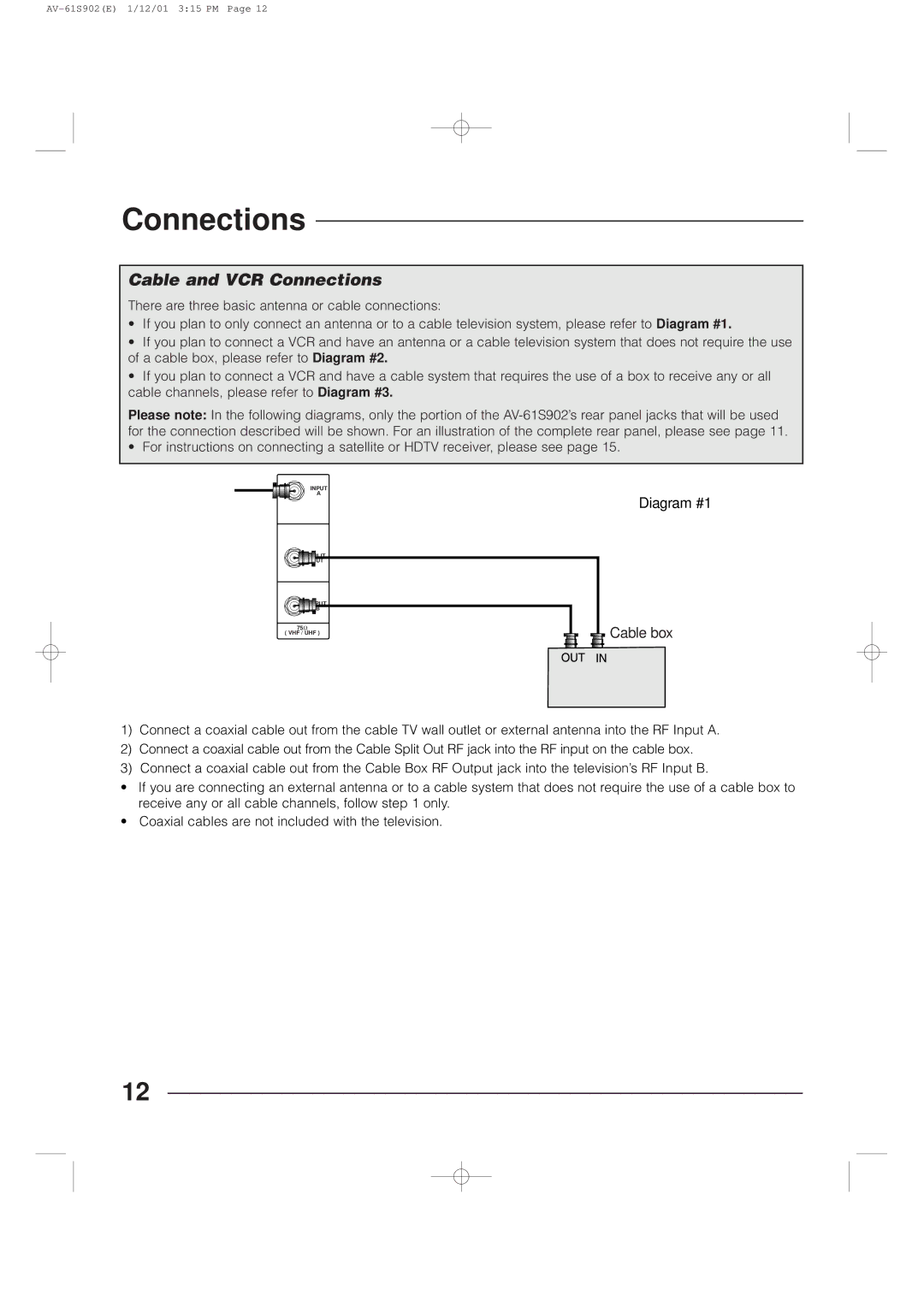
Diagram #1


 Cable box
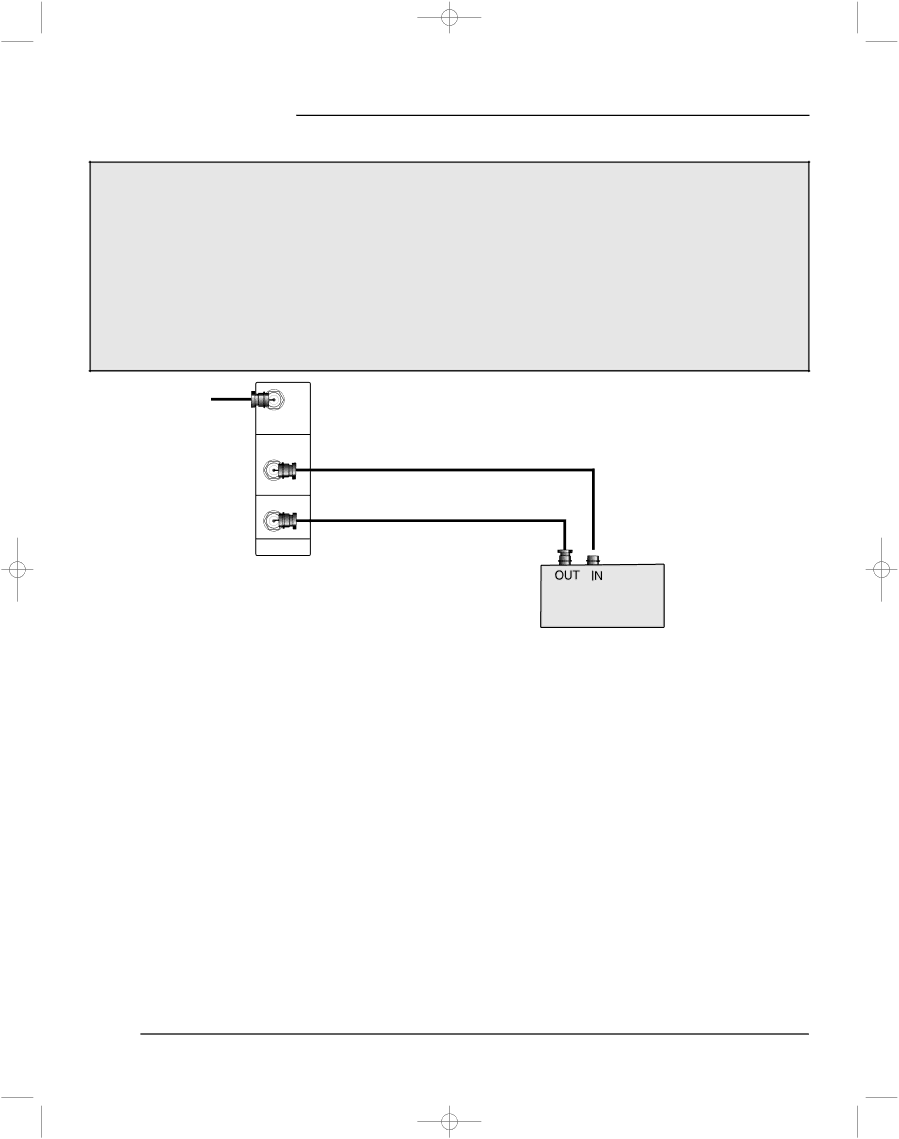
1)Connect a coaxial cable out from the cable TV wall outlet or external antenna into the RF Input A.
2)Connect a coaxial cable out from the Cable Split Out RF jack into the RF input on the cable box.
3)Connect a coaxial cable out from the Cable Box RF Output jack into the television’s RF Input B.
•If you are connecting an external antenna or to a cable system that does not require the use of a cable box to receive any or all cable channels, follow step 1 only.
•Coaxial cables are not included with the television.
12
