Parts Identification (Continued) |
|
|
q | w | e |
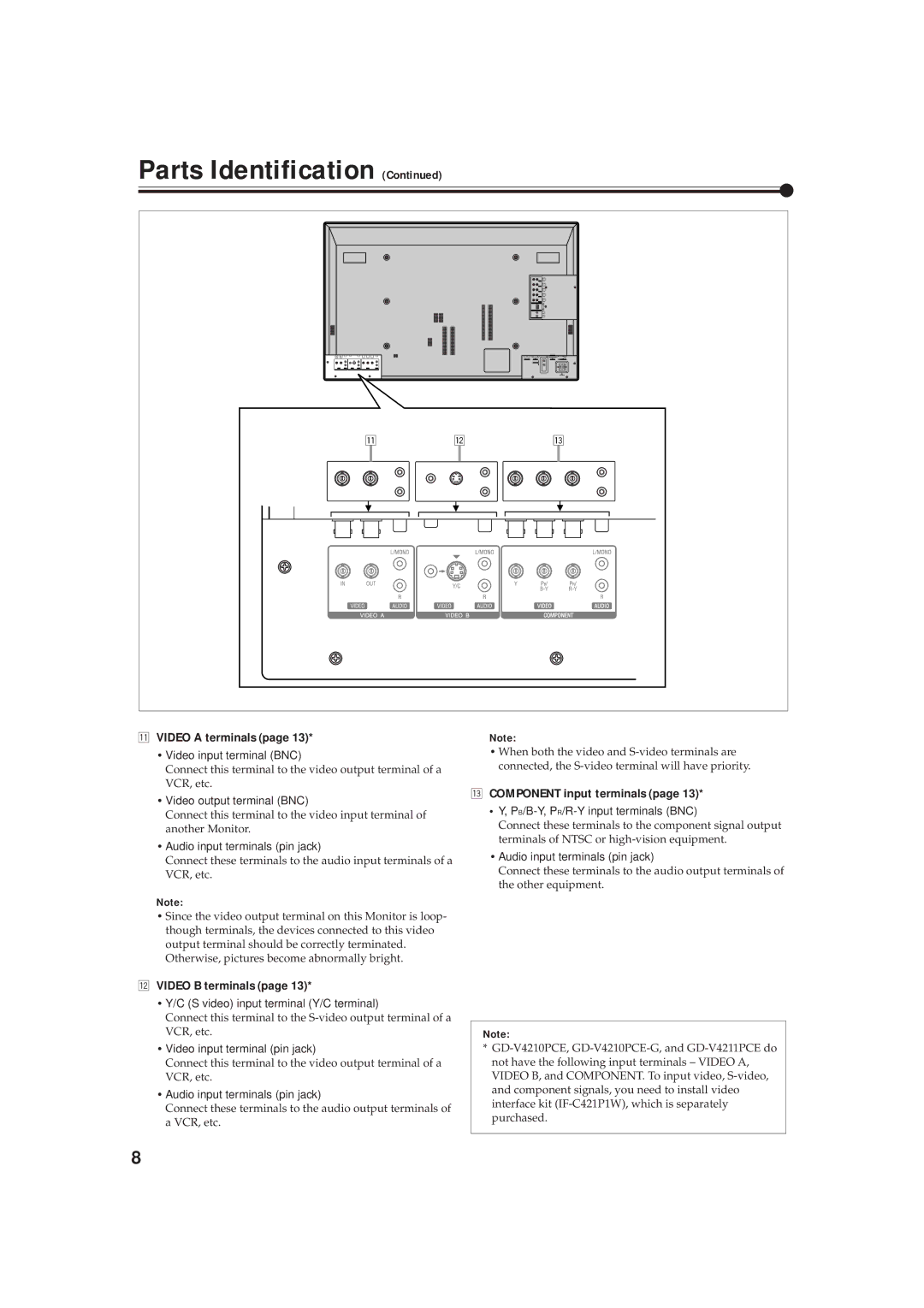
qVIDEO A terminals (page 13)*
•Video input terminal (BNC)
Connect this terminal to the video output terminal of a VCR, etc.
•Video output terminal (BNC)
Connect this terminal to the video input terminal of another Monitor.
•Audio input terminals (pin jack)
Connect these terminals to the audio input terminals of a VCR, etc.
Note:
•Since the video output terminal on this Monitor is loop- though terminals, the devices connected to this video output terminal should be correctly terminated. Otherwise, pictures become abnormally bright.
wVIDEO B terminals (page 13)*
•Y/C (S video) input terminal (Y/C terminal)
Connect this terminal to the
•Video input terminal (pin jack)
Connect this terminal to the video output terminal of a VCR, etc.
•Audio input terminals (pin jack)
Connect these terminals to the audio output terminals of a VCR, etc.
Note:
•When both the video and
eCOMPONENT input terminals (page 13)*
•Y, PB/B-Y, PR/R-Y input terminals (BNC)
Connect these terminals to the component signal output terminals of NTSC or
•Audio input terminals (pin jack)
Connect these terminals to the audio output terminals of the other equipment.
Note:
*
8