Controls, Connectors and Indicators
How to Attach
| V5000 | CK | |
| PA | ||
KA |
| ORK |
|
|
| ||
NETW |
| ||
1 | POWER | |
SUPPLY | ||
| ON | OFF |
|
| |
| NETWORKPACK | |
| KA- | |
|
| DV5000 |
7
8 |
|
3 |
|
5 |
|
B |
|
C | 4 |
D |
|
| ¡ |
| ™ |
9 |
|
6 |
|
A | 2 |
| |
| 0 |
Below is the procedure for attaching the main unit to the DV camcorder. Mount using the procedure shown below. 1 Turn off the camcorder power.
2Remove the battery case.
Remove the battery case mounting screws on the back of
☞ See page 35 of the
3Insert the connector wire of the camcorder through the back of the network pack to the front.
4Tilt the network pack diagonally, set the upper hooks on the
Caution Make sure the cushion does not shift
2
1 | VTR |
POWER | |
ON | OFF |
4 |
|
3
English
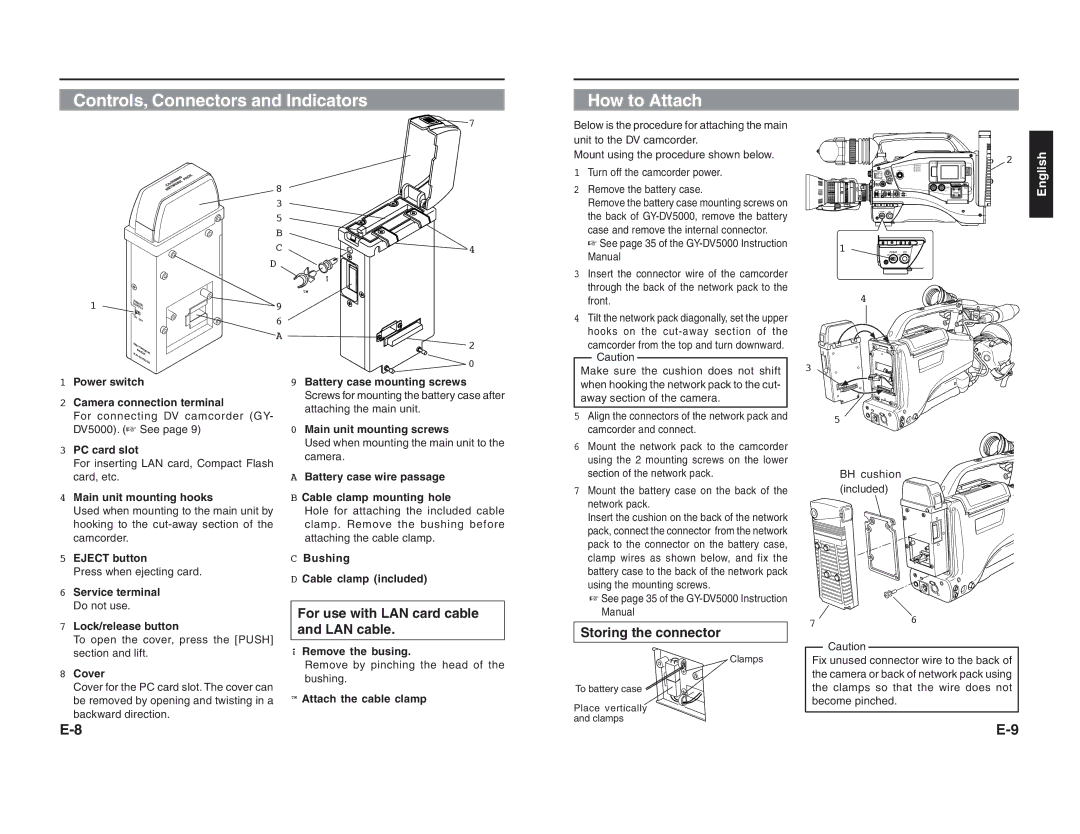
1Power switch
2Camera connection terminal
For connecting DV camcorder (GY- DV5000). (☞ See page 9)
3PC card slot
For inserting LAN card, Compact Flash card, etc.
4Main unit mounting hooks
Used when mounting to the main unit by hooking to the
5EJECT button
Press when ejecting card.
6Service terminal Do not use.
7Lock/release button
To open the cover, press the [PUSH] section and lift.
8Cover
Cover for the PC card slot. The cover can be removed by opening and twisting in a backward direction.
9Battery case mounting screws Screws for mounting the battery case after attaching the main unit.
0Main unit mounting screws
Used when mounting the main unit to the camera.
ABattery case wire passage
BCable clamp mounting hole
Hole for attaching the included cable clamp. Remove the bushing before attaching the cable clamp.
CBushing
DCable clamp (included)
For use with LAN card cable and LAN cable.
¡Remove the busing.
Remove by pinching the head of the bushing.
™Attach the cable clamp
when hooking the network pack to the cut- away section of the camera.
5Align the connectors of the network pack and camcorder and connect.
6Mount the network pack to the camcorder using the 2 mounting screws on the lower section of the network pack.
7Mount the battery case on the back of the network pack.
Insert the cushion on the back of the network pack, connect the connector from the network pack to the connector on the battery case, clamp wires as shown below, and fix the battery case to the back of the network pack using the mounting screws.
☞See page 35 of the
Storing the connector
Clamps
To battery case
Place vertically and clamps
5
BH cushion (included)
76
Caution Fix unused connector wire to the back of the camera or back of network pack using the clamps so that the wire does not become pinched.