Front-Panel Features and Indicators
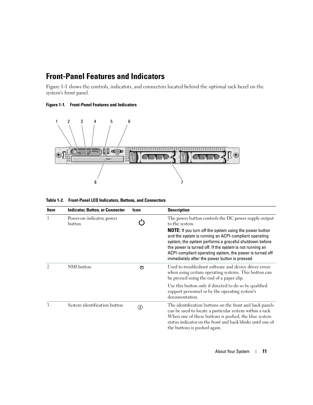
Figure 1-1 shows the controls, indicators, and connectors located behind the optional rack bezel on the system's front panel.
Figure 1-1. Front-Panel Features and Indicators
1 | 2 | 3 | 4 | 5 | 6 |
| 8 |
| 7 |
Table |
| ||
|
|
|
|
Item | Indicator, Button, or Connector | Icon | Description |
|
|
|
|
1 |
| The power button controls the DC power supply output | |
| button |
| to the system. |
NOTE: If you turn off the system using the power button and the system is running an
2 | NMI button | Used to troubleshoot software and device driver errors |
|
| when using certain operating systems. This button can |
|
| be pressed using the end of a paper clip. |
|
| Use this button only if directed to do so by qualified |
|
| support personnel or by the operating system's |
|
| documentation. |
|
|
|
3 | System identification button | The identification buttons on the front and back panels |
|
| can be used to locate a particular system within a rack. |
|
| When one of these buttons is pushed, the blue system |
|
| status indicator on the front and back blinks until one of |
|
| the buttons is pushed again. |
About Your System
11