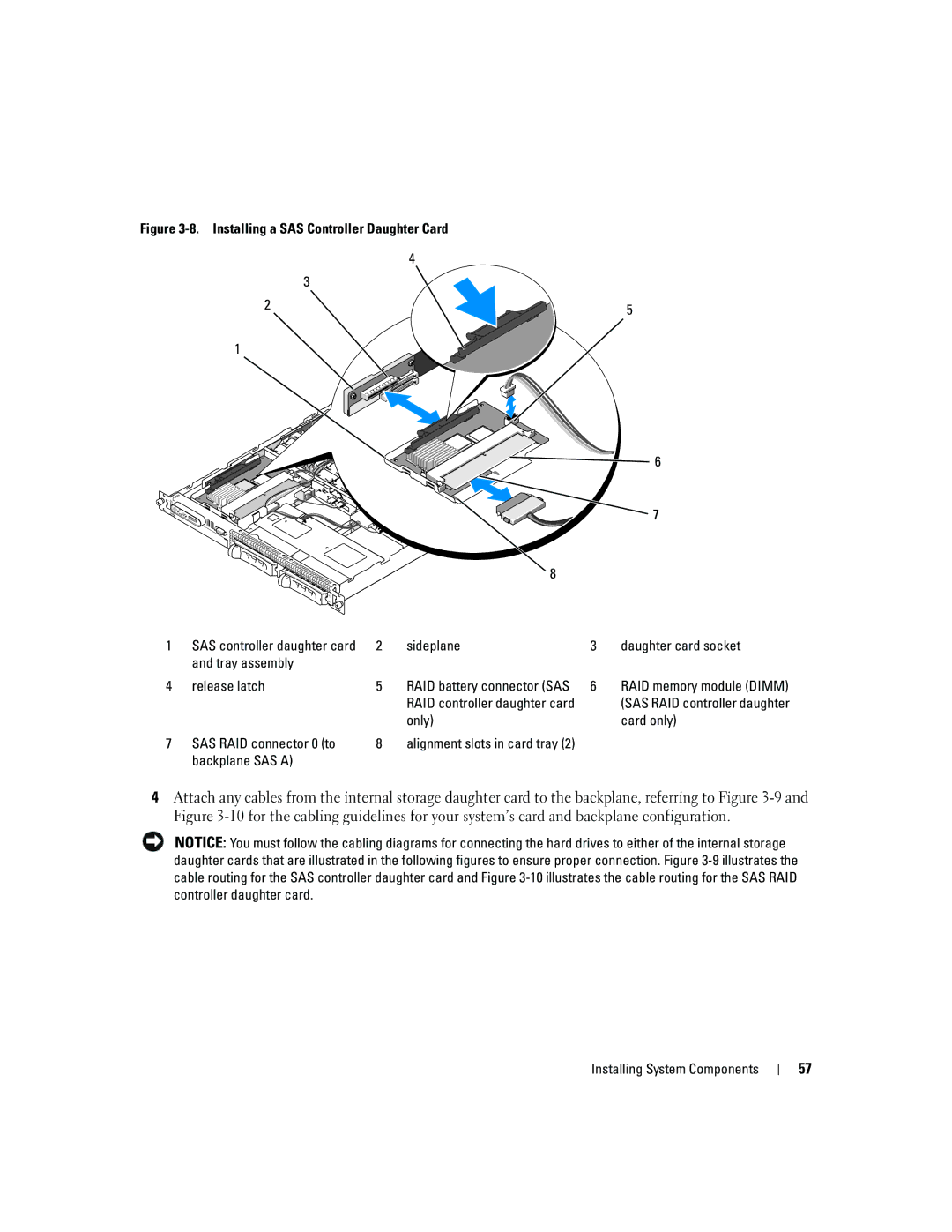
Figure 3-8. Installing a SAS Controller Daughter Card
4
3
2 | 5 |
|
1
6 |
7
|
|
| 8 |
|
|
1 | SAS controller daughter card | 2 | sideplane | 3 | daughter card socket |
| and tray assembly |
|
|
|
|
4 | release latch | 5 | RAID battery connector (SAS | 6 | RAID memory module (DIMM) |
|
|
| RAID controller daughter card |
| (SAS RAID controller daughter |
|
|
| only) |
| card only) |
7 | SAS RAID connector 0 (to | 8 | alignment slots in card tray (2) |
|
|
| backplane SAS A) |
|
|
|
|
4Attach any cables from the internal storage daughter card to the backplane, referring to Figure
NOTICE: You must follow the cabling diagrams for connecting the hard drives to either of the internal storage daughter cards that are illustrated in the following figures to ensure proper connection. Figure
Installing System Components
57