Network pack setup | Controlling |
With the Network Pack,
It is also possible to playback video and audio from
as well as save data to files. However, note that video and audio from
Network pack setup | CAM & VTR CONTROL screen |
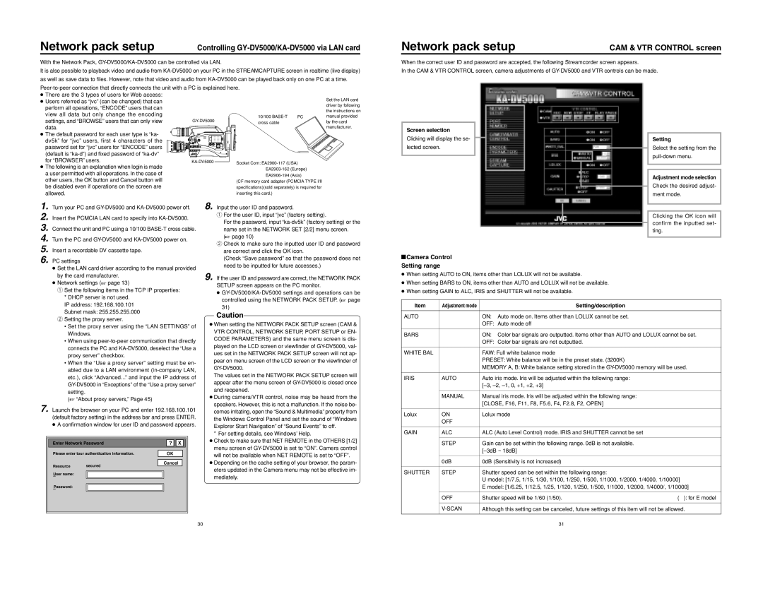
When the correct user ID and password are accepted, the following Streamcorder screen appears.
In the CAM & VTR CONTROL screen, camera adjustments of
●There are the 3 types of users for Web access:
●Users referred as “jvc” (can be changed) that can perform all operations, “ENCODE” users that can view all data but only change the encoding
settings, and “BROWSE” users that can only view data.
● The default password for each user type is “ka- dv5k” for “jvc” users, first 4 characters of the password set for “jvc” users for “ENCODE” users (default is
●The following is an explanation when login is made a user permitted with all operations. In the case of other users, the OK button and Cancel button will be disabled even if operations on the screen are allowed.
1. Turn your PC and
2. Insert the PCMCIA LAN card to specify into
3. Connect the unit and PC using a 10/100
4. Turn the PC and
5. Insert a recordable DV cassette tape.
6. PC settings
● Set the LAN card driver according to the manual provided by the card manufacturer.
● Network settings (☞ page 13)
q Set the following items in the TCP IP properties:
|
|
| Set the LAN card |
|
|
| driver by following |
|
|
| the instructions on |
10/100 | PC | manual provided | |
cross cable |
|
| by the card |
|
|
| manufacturer. |
|
|
|
|
|
|
|
|
Screen selection
Clicking will display the se- lected screen.
\Camera Control Setting range
●When setting AUTO to ON, items other than LOLUX will not be available.
●When setting BARS to ON, items other than AUTO and LOLUX will not be available.
●When setting GAIN to ALC, IRIS and SHUTTER will not be available.
Setting
Select the setting from the
Adjustment mode selection
Check the desired adjust-
ment mode.
Clicking the OK icon will confirm the inputted set- ting.
* DHCP server is not used. |
|
IP address: 192.168.100.101 |
|
Subnet mask: 255.255.255.000 |
|
w Setting the proxy server. | Caution |
| |
• Set the proxy server using the “LAN SETTINGS” of |
|
Windows.
• When using
• When the “Use a proxy server” setting must be en- abled due to a LAN environment
(☞ “About proxy servers,” Page 45)
7. Launch the browser on your PC and enter 192.168.100.101 (default factory setting) in the address bar and press ENTER. ● A confirmation window for user ID and password appears.
Enter Network Password |
| ? | X |
| ||
|
|
|
|
| ||
Please enter tour authentication information. |
| OK |
| |||
|
|
|
|
| ||
Resource | secured |
| Cancel |
| ||
|
|
|
|
| ||
User name:
Password:
Item | Adjustment mode |
| Setting/description |
|
|
|
|
|
|
AUTO |
| ON: | Auto mode on. Items other than LOLUX cannot be set. |
|
|
| OFF: | Auto mode off |
|
|
|
|
| |
BARS |
| ON: | Color bar signals are outputted. Items other than AUTO and LOLUX cannot be set. | |
|
| OFF: Color bar signals are not outputted. |
| |
|
|
|
| |
WHITE BAL |
| FAW: Full white balance mode |
| |
|
| PRESET: White balance will be in the preset state. (3200K) |
| |
|
| MEMORY A, B: White balance setting stored in the | ||
|
|
|
| |
IRIS | AUTO | Auto iris mode. Iris will be adjusted within the following range: |
| |
|
|
| ||
|
|
|
| |
| MANUAL | Manual iris mode. Iris will be adjusted within the following range: |
| |
|
| [CLOSE, F16, F11, F8, F5.6, F4, F2.8, F2, OPEN] |
| |
|
|
|
| |
Lolux | ON | Lolux mode |
| |
| OFF |
|
|
|
|
|
|
| |
GAIN | ALC | ALC (Auto Level Control) mode. IRIS and SHUTTER cannot be set |
| |
|
|
|
| |
| STEP | Gain can be set within the following range. 0dB is not available. |
| |
|
|
| ||
|
|
|
| |
| 0dB | 0dB (Sensitivity is not increased) |
| |
|
|
|
| |
SHUTTER | STEP | Shutter speed can be set within the following range: |
| |
|
| U model: [1/7.5, 1/15, 1/30, 1/100, 1/250, 1/500, 1/1000, 1/2000, 1/4000, 1/10000] | ||
|
| E model: [1/6.25, 1/12.5, 1/25, 1/120, 1/250, 1/500, 1/1000, 1/2000, 1/4000/, 1/10000] | ||
|
|
|
| |
| OFF | Shutter speed will be 1/60 (1/50). | ( ): for E model | |
|
|
| ||
| Although this setting can be canceled, future settings of this item will not be allowed. | |||
|
|
|
|
|
30 | 31 |