For an analogue decoder
To watch through or to record a scrambled program on your VCR, connect the analogue decoder to your VCR and select the scrambled channel on your VCR.
If there is not an appropriate terminal for the decoder connection on your VCR, connect the decoder to your TV.
Refer also to the manuals supplied with these components.
For T-V LINK
•You can use the
•Connect a SCART cable to
•Some video components support the data communication like
Audio/video connection
In addition to the SCART terminals, this receiver is equipped with the following video terminals:
•Component video input/output: VIDEO IN, DVR/DVD IN, MONITOR OUT
•Composite and
IMPORTANT:
The component video signals from the COMPONENT jacks are transmitted only through the MONITOR OUT jacks.
Therefore, if the TV is connected to the receiver through the SCART terminal (TV) and a playing video component is connected to the receiver through the component video jacks (VIDEO IN or DVR/DVD IN), you cannot view the playback picture on the TV.
7Connecting a DVD recorder or DVD player to the DVR/DVD IN jacks
To fully enjoy Dolby Digital and DTS
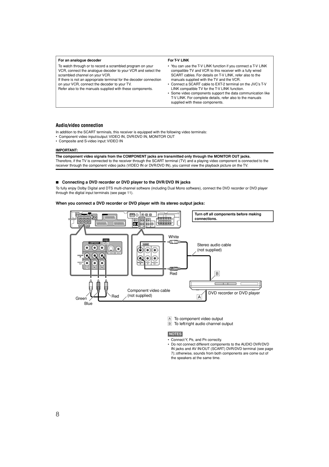
When you connect a DVD recorder or DVD player with its stereo output jacks:
Turn off all components before making connections.
White
VIDEO
COMPONENT | VIDEO IN |
| AUDIO |
|
|
|
|
| |
|
|
|
| L |
| VIDEO |
|
| |
DVR/DVD |
|
|
|
|
IN |
|
|
| R |
|
|
|
| |
MONITOR |
| DVR/DVD | VIDEO | MONITOR |
OUT |
| IN | IN | OUT |
Y PBPR
Red
|
| Component video cable |
Green | Red | (not supplied) |
|
| |
Blue |
|
|
Stereo audio cable (not supplied)
ı
DVD recorder or DVD player
Å
ÅTo component video output
ıTo left/right audio channel output
NOTES
•Connect Y, PB, and PR correctly.
•Do not connect different components to the AUDIO DVR/DVD IN jacks and AV IN/OUT (SCART) DVR/DVD terminal (see page 7); otherwise, sounds from both components are come out of the speakers at the same time.
8