PREPARATIONS AND MAIN FUNCTIONS
INTERCOM
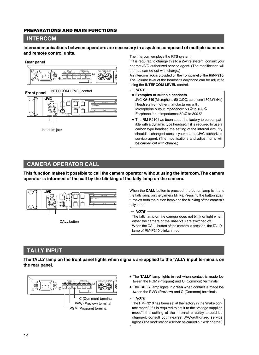
Intercommunications between operators are necessary in a system composed of multiple cameras and remote control units.
Rear panel
| TALLY |
|
| INTERCOM | AUX VIDEO INPUT | G |
PGM | PVW | C | H | C | G |
|
|
|
|
|
| RTS |
|
Front panel | INTERCOM LEVEL control | |||
|
|
|
| |
| TALLY | CALL | FULL AUTO | F1 |
|
|
|
| SHUTTER |
|
|
|
| 2. CABLE |
|
|
| BARS | F2 |
|
|
|
| GAIN |
|
| INTERCOM |
|
|
|
| LEVEL |
|
|
The intercom employs the RTS system.
If it is required to change this to a
An intercom jack is provided on the front panel of the
NOTE
●Examples of suitable headsets
JVC
Microphone output impedance: 50 W to 100 W
Earphone input impedance: 50 W to 300 W
● The
Intercom jackcarbon type headset, the setting of the internal circuitry should be changed; consult your nearest
CAMERA OPERATOR CALL
This function makes it possible to call the camera operator without using the intercom. The camera operator is informed of the call by the blinking of the tally lamp on the camera.
TALLY CALL | FULL AUTO | F1 |
| SHUTTER |
| 2. CABLE |
BARS | F2 |
| GAIN |
INTERCOM |
|
LEVEL |
|
CALL button
When the CALL button is pressed, the button lamp is lit and the tally lamp on the camera blinks. Pressing the button again turns off both the button lamp and the blinking of the camera’s tally lamp.
NOTE
The tally lamp on the camera does not blink or light when either the camera or the
TALLY INPUT
The TALLY lamp on the front panel lights when signals are applied to the TALLY input terminals on the rear panel.
| TALLY |
|
| INTERCOM | AUX VIDEO INPUT | G |
PGM | PVW | C | H | C | G |
|
|
|
|
|
| RTS |
|
C (Common) terminal
PVW (Preview) terminal
PGM (Program) terminal
●The TALLY lamp lights in red when contact is made be- tween the PGM (Program) and C (Common) terminals.
●The TALLY lamp lights in green when contact is made be- tween the PVW (Preview) and C (Common) terminals.
NOTE
The
14
