Introduction
Name and Function of Parts (continued)
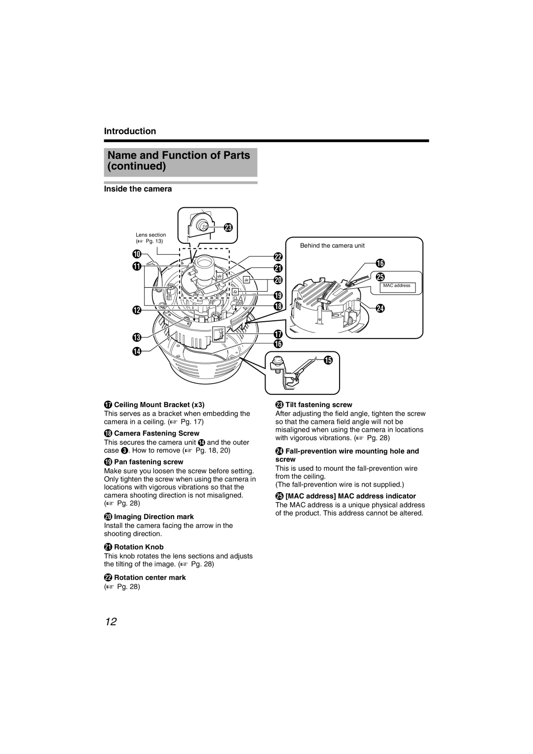
Inside the camera
![]() W
W
Lens section (A Pg. 13)
J
K ![]()
L |
M
N
Q Ceiling Mount Bracket (x3)
This serves as a bracket when embedding the camera in a ceiling. (A Pg. 17)
R Camera Fastening Screw
This secures the camera unit N and the outer case C. How to remove (A Pg. 18, 20)
S Pan fastening screw
Make sure you loosen the screw before setting. Only tighten the screw when using the camera in locations with vigorous vibrations so that the camera shooting direction is not misaligned. (A Pg. 28)
T Imaging Direction mark
Install the camera facing the arrow in the shooting direction.
U Rotation Knob
This knob rotates the lens sections and adjusts the tilting of the image. (A Pg. 28)
V Rotation center mark
(A Pg. 28)
Behind the camera unit
V
UP
T ![]()
![]() Y
Y
MAC address
S
R ![]()
![]()
![]()
![]() X
X
Q
P
![]() O
O
W Tilt fastening screw
After adjusting the field angle, tighten the screw so that the camera field angle will not be misaligned when using the camera in locations with vigorous vibrations. (A Pg. 28)
XFall-prevention wire mounting hole and screw
This is used to mount the
(The
Y[MAC address] MAC address indicator The MAC address is a unique physical address of the product. This address cannot be altered.
12
