Controls, Indicators, Displays and Connections
In this section you will find a short description of all controls, indicators, displays and connections. The button symbols used here are also used in the description of the operating steps.
Front view
(Panel folded down)
1 | 2 | 3 | 4 |
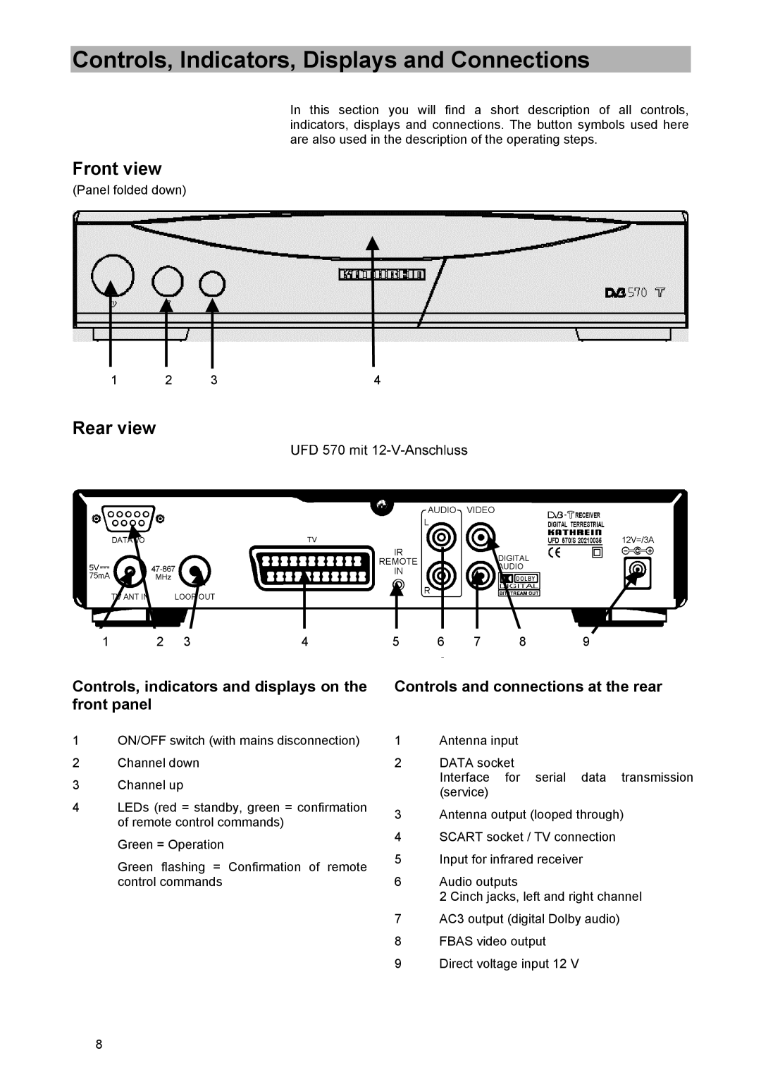
Rear view
1 | 2 | 3 | 4 | 5 | 6 | 7 | 8 | 9 |
Controls, indicators and displays on the front panel
1ON/OFF switch (with mains disconnection)
2Channel down
3Channel up
4LEDs (red = standby, green = confirmation of remote control commands)
Green = Operation
Green flashing = Confirmation of remote control commands
Controls and connections at the rear
1Antenna input
2DATA socket
Interface for serial data transmission (service)
3Antenna output (looped through)
4SCART socket / TV connection
5Input for infrared receiver
6Audio outputs
2 Cinch jacks, left and right channel
7AC3 output (digital Dolby audio)
8FBAS video output
9Direct voltage input 12 V
8