HYDRAULIC LIFT OPERATION
REEL/WING - LIFT SEQUENCE
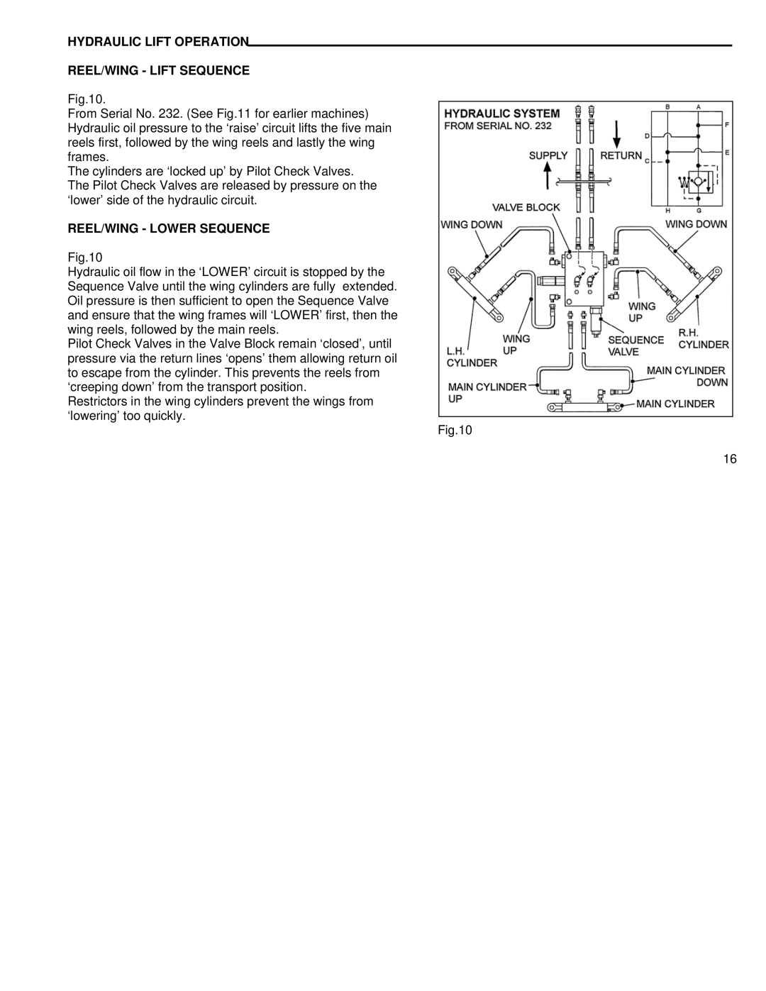
Fig.10.
From Serial No. 232. (See Fig.11 for earlier machines) Hydraulic oil pressure to the ‘raise’ circuit lifts the five main reels first, followed by the wing reels and lastly the wing frames.
The cylinders are ‘locked up’ by Pilot Check Valves. The Pilot Check Valves are released by pressure on the ‘lower’ side of the hydraulic circuit.
REEL/WING - LOWER SEQUENCE
Fig.10
Hydraulic oil flow in the ‘LOWER’ circuit is stopped by the Sequence Valve until the wing cylinders are fully extended. Oil pressure is then sufficient to open the Sequence Valve and ensure that the wing frames will ‘LOWER’ first, then the wing reels, followed by the main reels.
Pilot Check Valves in the Valve Block remain ‘closed’, until pressure via the return lines ‘opens’ them allowing return oil to escape from the cylinder. This prevents the reels from ‘creeping down’ from the transport position.
Restrictors in the wing cylinders prevent the wings from ‘lowering’ too quickly.
Fig.10
16