LIFT CHAIN ADJUSTMENTS
Fig.14
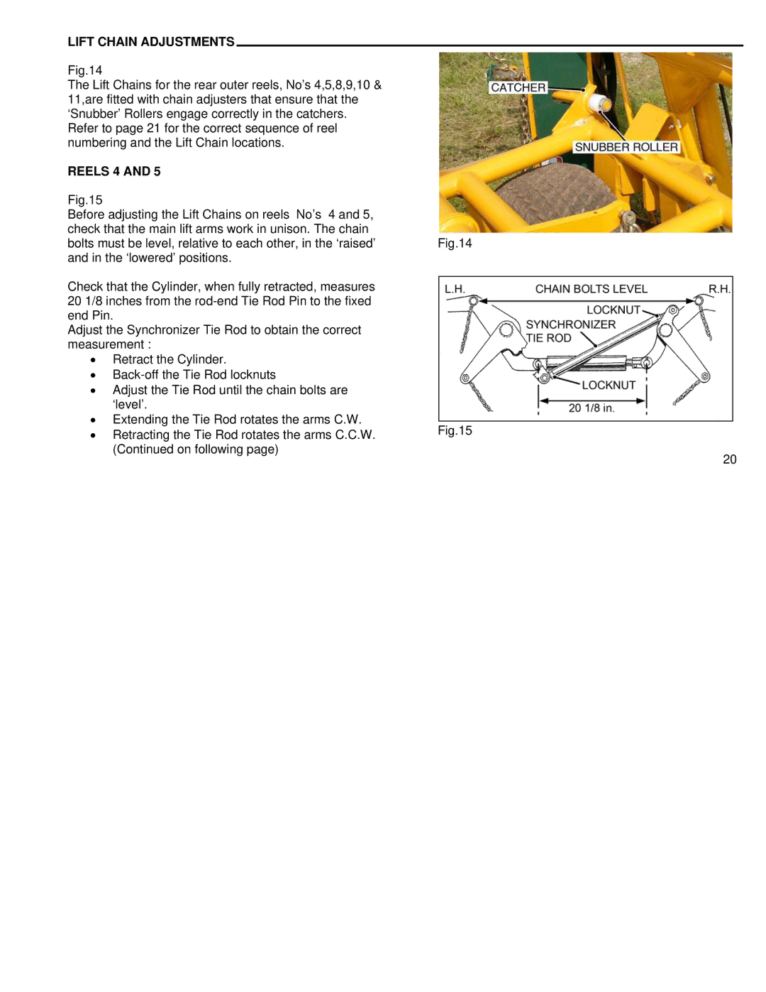
The Lift Chains for the rear outer reels, No’s 4,5,8,9,10 & 11,are fitted with chain adjusters that ensure that the ‘Snubber’ Rollers engage correctly in the catchers. Refer to page 21 for the correct sequence of reel numbering and the Lift Chain locations.
REELS 4 AND 5
Fig.15
Before adjusting the Lift Chains on reels No’s 4 and 5, check that the main lift arms work in unison. The chain bolts must be level, relative to each other, in the ‘raised’ and in the ‘lowered’ positions.
Check that the Cylinder, when fully retracted, measures 20 1/8 inches from the
Adjust the Synchronizer Tie Rod to obtain the correct measurement :
•Retract the Cylinder.
•
•Adjust the Tie Rod until the chain bolts are ‘level’.
•Extending the Tie Rod rotates the arms C.W.
•Retracting the Tie Rod rotates the arms C.C.W. (Continued on following page)
Fig.14
Fig.15
20