HYDRAULIC LIFT OPERATION
SEQUENCE VALVE MANIFOLD, RELIEF VALVE
SETTING
To prevent damage to the lift linkage if there is a ‘hang- up’ of a Lift Chain, a Relief Valve is installed in the Manifold Block to control oil pressure to the Lift Cylinders.
The Relief Valve setting prevents excessive oil pressure at the Lift Cylinders at engine ‘idle speed’.
Higher ‘idle speeds’ will not increase the ‘lift rate’, this is controlled by Restrictor Orifices in each cylinder.
Idle speed settings that are ‘too fast’ increase the oil flow above the Relief Valve setting, negating its protection.
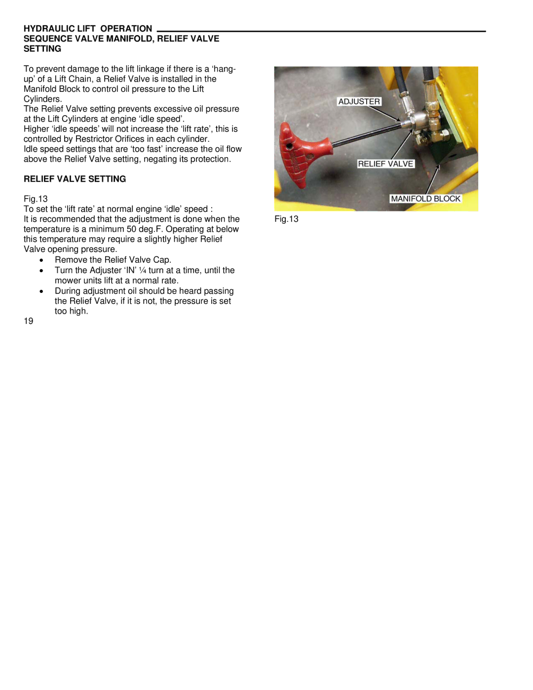
RELIEF VALVE SETTING
Fig.13
To set the ‘lift rate’ at normal engine ‘idle’ speed :
It is recommended that the adjustment is done when the Fig.13 temperature is a minimum 50 deg.F. Operating at below
this temperature may require a slightly higher Relief Valve opening pressure.
•Remove the Relief Valve Cap.
•Turn the Adjuster ‘IN’ ¼ turn at a time, until the mower units lift at a normal rate.
•During adjustment oil should be heard passing the Relief Valve, if it is not, the pressure is set too high.
19