Connecting Wires to Terminals
■Connector Function Guide
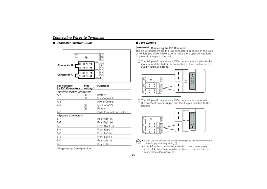
■Plug Setting
![]()
![]() Connecting the ISO Connector
Connecting the ISO Connector
Connector B
Connector A
|
|
| 10 |
1 | 3 | 5 | 7 |
2 | 4 | 6 | 8 |
1 | 3 | 5 | 7 |
2 | 4 | 6 | 8 |
The pin arrangement for the ISO connectors depends on the type of vehicle you drive. Make sure to make the proper connections to prevent damage to the unit.
1The
Pin Numbers | Plug | Functions |
for ISO Connectors | setting* |
|
<External Power Connector> |
| |
1 | Battery | |
| 2 | Ignition (ACC) |
| Power Control | |
1 | Ignition (ACC) | |
| 2 | Battery |
| Earth (Ground) Connection | |
<Speaker Connector> |
|
|
| Rear Right (+) | |
| Rear Right | |
| Front Right (+) | |
| Front Right | |
| Front Left (+) | |
| Front Left | |
| Rear Left (+) | |
| Rear Left | |
*Plug setting: See right side.
2The
10 |
• If both the
•If the
— 25 —