6 MEMORY CHANNELS
Channel 0 ~ 399 | a | Channel 0 ~ 399 | |
|
|
| |
Receive frequency | a | Receive frequency | |
|
|
| |
Transmit frequency | a | Transmit frequency | |
|
|
| |
Tone frequency | a | Tone frequency | |
|
|
| |
Offset direction | a | Offset direction | |
|
|
| |
CTCSS frequency | a | CTCSS frequency | |
|
|
| |
DCS code | a | DCS code | |
|
|
| |
Tone/ CTCSS/ DCS | a | Tone/ CTCSS/ DCS | |
ON/ OFF status |
| ON/ OFF status | |
Offset frequency | a | Offset frequency | |
|
|
| |
Reverse ON | a | Reverse ON | |
|
|
| |
Frequency step size | a | Frequency step size | |
|
|
| |
Memory channel | a | Memory channel | |
name | name | ||
| |||
Fine Tuning ON | a | Fine Tuning ON | |
|
|
| |
Mode selection | a | Mode selection | |
|
|
| |
Memory Channel | a | Memory Channel | |
Lockout ON/ OFF | Lockout ON/ OFF | ||
|
|
| |
Channel 0 ~ 399 | a | L0/U0 ~ L9/U9, Pr1, | |
|
| Pr2 and | |
Receive frequency | a | Receive frequency | |
|
|
| |
Transmit frequency | a | Transmit frequency | |
|
|
| |
Tone frequency | a | Tone frequency | |
|
|
| |
Offset direction | a | Offset direction | |
|
|
| |
CTCSS frequency | a | CTCSS frequency | |
|
|
| |
DCS code | a | DCS code | |
|
|
| |
Tone/ CTCSS/ DCS | a | Tone/ CTCSS/ DCS | |
ON/ OFF status |
| ON/ OFF status | |
Offset frequency | a | Offset frequency | |
|
|
| |
Reverse ON | a | Reverse ON | |
|
|
| |
Frequency step size | a | Frequency step size | |
|
|
| |
Memory channel | a | Memory channel | |
name | name | ||
| |||
Fine Tuning ON | a | Fine Tuning ON | |
|
|
| |
Mode selection | a | Mode selection | |
|
|
| |
Memory Channel | a | Memory Channel | |
Lockout ON | Lockout OFF | ||
|
The tables above illustrate how data is transferred between memory channels.
Note: When transferring an
CALL CHANNEL
The Call channel can be recalled instantly no matter what frequency the transceiver is operating on. For instance, you may use the Call channel as an emergency channel within your group. In this case, the Call Scan {page 25} will be useful.
The default Call channel frequencies are 144.000 MHz for the 2 m band, 223.000 MHz for
1.25m band
Note: Unlike Memory channels 0 to 399, the Call channel cannot be cleared. Clearing the Call channel will set it to the factory default values.
RECALLING THE CALL CHANNEL
1Press [BAND] to select an amateur radio band.
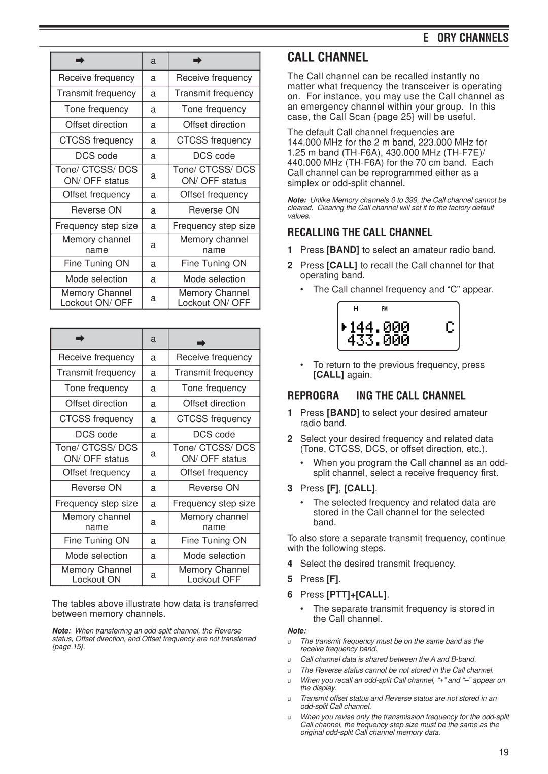
2Press [CALL] to recall the Call channel for that operating band.
• The Call channel frequency and “C” appear.
•To return to the previous frequency, press [CALL] again.
REPROGRAMMING THE CALL CHANNEL
1Press [BAND] to select your desired amateur radio band.
2Select your desired frequency and related data (Tone, CTCSS, DCS, or offset direction, etc.).
•When you program the Call channel as an odd- split channel, select a receive frequency first.
3Press [F], [CALL].
•The selected frequency and related data are stored in the Call channel for the selected band.
To also store a separate transmit frequency, continue with the following steps.
4Select the desired transmit frequency.
5Press [F].
6Press [PTT]+[CALL].
•The separate transmit frequency is stored in the Call channel.
Note:
◆The transmit frequency must be on the same band as the receive frequency band.
◆Call channel data is shared between the A and
◆The Reverse status cannot be not stored in the Call channel.
◆When you recall an
◆Transmit offset status and Reverse status are not stored in an
◆When you revise only the transmission frequency for the
19
