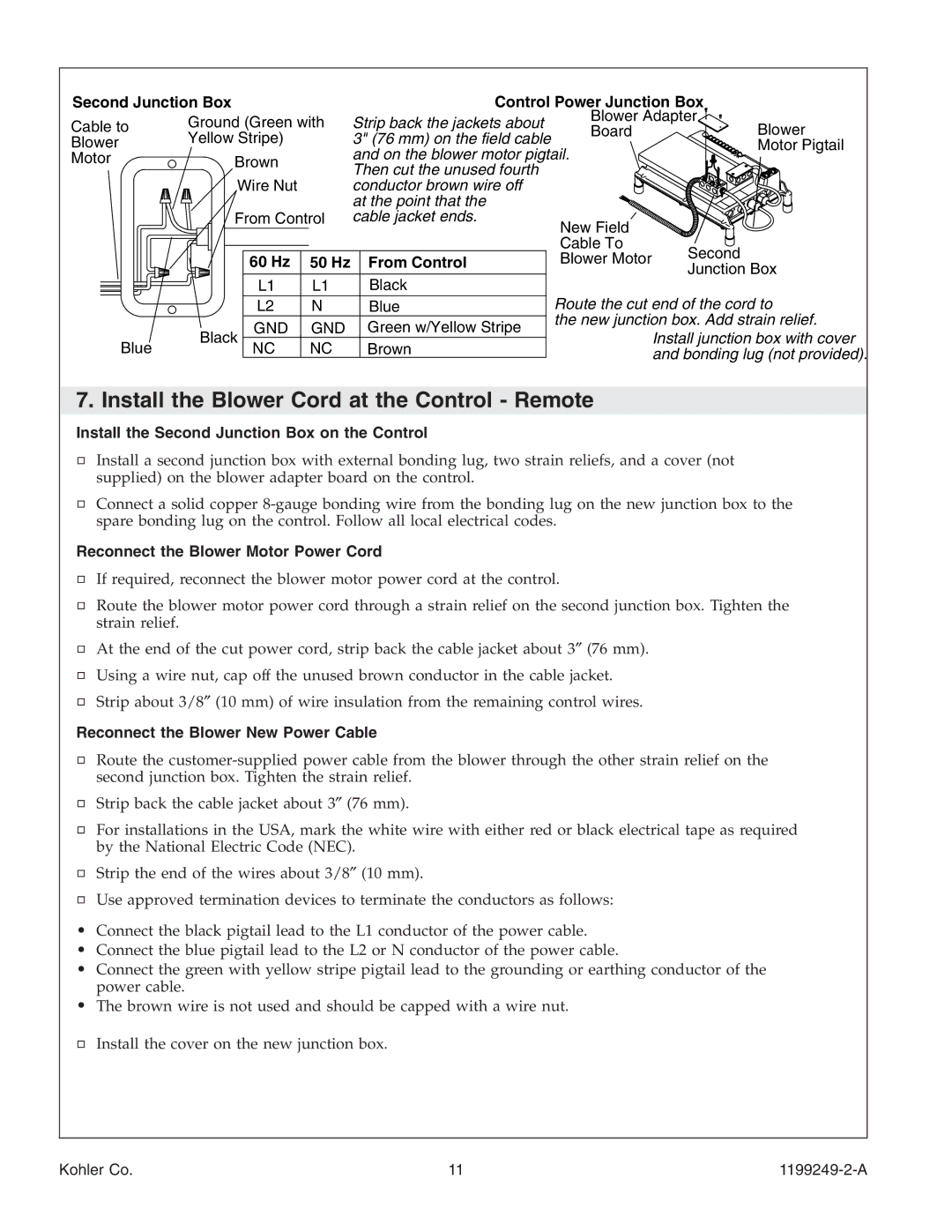
Second Junction Box
Cable to | Ground (Green with | |
Yellow Stripe) | ||
Blower | ||
Motor | Brown | |
| Wire Nut | |
| From Control |
Control Power Junction Box
Strip back the jackets about | Blower Adapter | |
Board | ||
3" (76 mm) on the field cable | ||
| ||
and on the blower motor pigtail. |
| |
Then cut the unused fourth |
| |
conductor brown wire off |
| |
at the point that the |
| |
cable jacket ends. |
|
Blower Motor Pigtail
|
| 60 Hz | 50 Hz | From Control |
|
| L1 | L1 | Black |
|
| L2 | N | Blue |
| Black | GND | GND | Green w/Yellow Stripe |
Blue | NC | NC | Brown |
Second
Junction Box
Route the cut end of the cord to
the new junction box. Add strain relief.
Install junction box with cover and bonding lug (not provided).
7. Install the Blower Cord at the Control - Remote
Install the Second Junction Box on the Control
Install a second junction box with external bonding lug, two strain reliefs, and a cover (not supplied) on the blower adapter board on the control.
Connect a solid copper
Reconnect the Blower Motor Power Cord
If required, reconnect the blower motor power cord at the control.
Route the blower motor power cord through a strain relief on the second junction box. Tighten the strain relief.
At the end of the cut power cord, strip back the cable jacket about 3″ (76 mm).
Using a wire nut, cap off the unused brown conductor in the cable jacket. Strip about 3/8″ (10 mm) of wire insulation from the remaining control wires.
Reconnect the Blower New Power Cable
Route the
Strip back the cable jacket about 3″ (76 mm).
For installations in the USA, mark the white wire with either red or black electrical tape as required by the National Electric Code (NEC).
Strip the end of the wires about 3/8″ (10 mm).
Use approved termination devices to terminate the conductors as follows:
•Connect the black pigtail lead to the L1 conductor of the power cable.
•Connect the blue pigtail lead to the L2 or N conductor of the power cable.
•Connect the green with yellow stripe pigtail lead to the grounding or earthing conductor of the power cable.
•The brown wire is not used and should be capped with a wire nut.
Install the cover on the new junction box.
Kohler Co. | 11 |