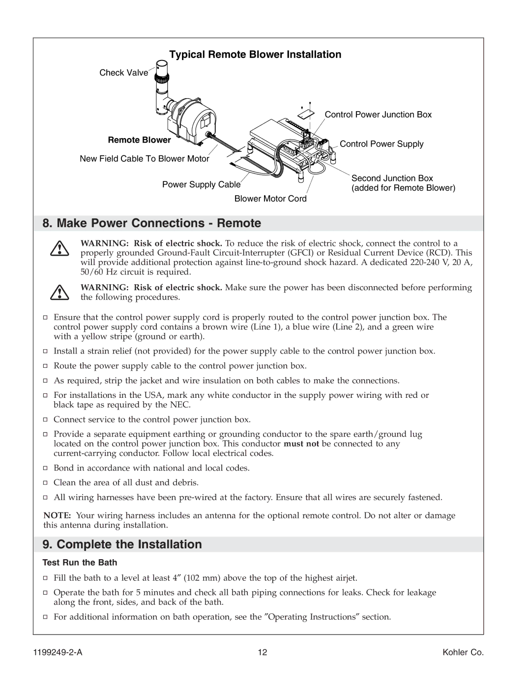
Typical Remote Blower Installation
Check Valve
Control Power Junction Box
Remote Blower
New Field Cable To Blower Motor
Power Supply Cable
Blower Motor Cord
Control Power Supply
Second Junction Box (added for Remote Blower)
8. Make Power Connections - Remote
WARNING: Risk of electric shock. To reduce the risk of electric shock, connect the control to a properly grounded
WARNING: Risk of electric shock. Make sure the power has been disconnected before performing the following procedures.
Ensure that the control power supply cord is properly routed to the control power junction box. The control power supply cord contains a brown wire (Line 1), a blue wire (Line 2), and a green wire with a yellow stripe (ground or earth).
Install a strain relief (not provided) for the power supply cable to the control power junction box.
Route the power supply cable to the control power junction box.
As required, strip the jacket and wire insulation on both cables to make the connections.
For installations in the USA, mark any white conductor in the supply power wiring with red or black tape as required by the NEC.
Connect service to the control power junction box.
Provide a separate equipment earthing or grounding conductor to the spare earth/ground lug located on the control power junction box. This conductor must not be connected to any
Bond in accordance with national and local codes.
Clean the area of all dust and debris.
All wiring harnesses have been
NOTE: Your wiring harness includes an antenna for the optional remote control. Do not alter or damage this antenna during installation.
9. Complete the Installation
Test Run the Bath
Fill the bath to a level at least 4″ (102 mm) above the top of the highest airjet.
Operate the bath for 5 minutes and check all bath piping connections for leaks. Check for leakage along the front, sides, and back of the bath.
For additional information on bath operation, see the ″Operating Instructions″ section.
12 | Kohler Co. |
