Land Pride
Section 3: Adjustments
Center and Wing Section Leveling
These adjustments should be made with the cutter hooked up to the same tractor that will be used for field operations or one having the same drawbar height. Cutter adjusting rods are set at the factory prior to shipment. The adjusting rods control the draw bar height at the hitch clevis.
Refer to Figure 3-1, Figure 3-2 & Figure 3-3:
1.Attach the cutter to the tractor and position it on level ground.
2.Raise both wings to locked position.
3.See Figure
23574 | Front Skid |
Front Skid Position
Figure
4.See Figure
5.Repeat steps 3 and 4 for the right hand leveling rod. Be sure that both left and right leveling rods are equally tight.
6.See Figure
5 4
1
15285
Wing Leveling Turnbuckle
Figure
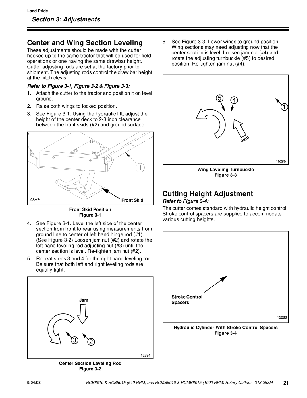
Cutting Height Adjustment
Refer to Figure 3-4:
The cutter comes standard with hydraulic height control. Stroke control spacers are supplied to accommodate various cutting heights.
Jam
3 2
15284
Center Section Leveling Rod
Figure
Stroke Control
Spacers
15286
Hydraulic Cylinder With Stroke Control Spacers
Figure
9/04/08 | RCB6010 & RCB6015 (540 RPM) and RCMB6010 & RCMB6015 (1000 RPM) Rotary Cutters | 21 |