Table of Contents
Section 3 Adjustments
Land Pride
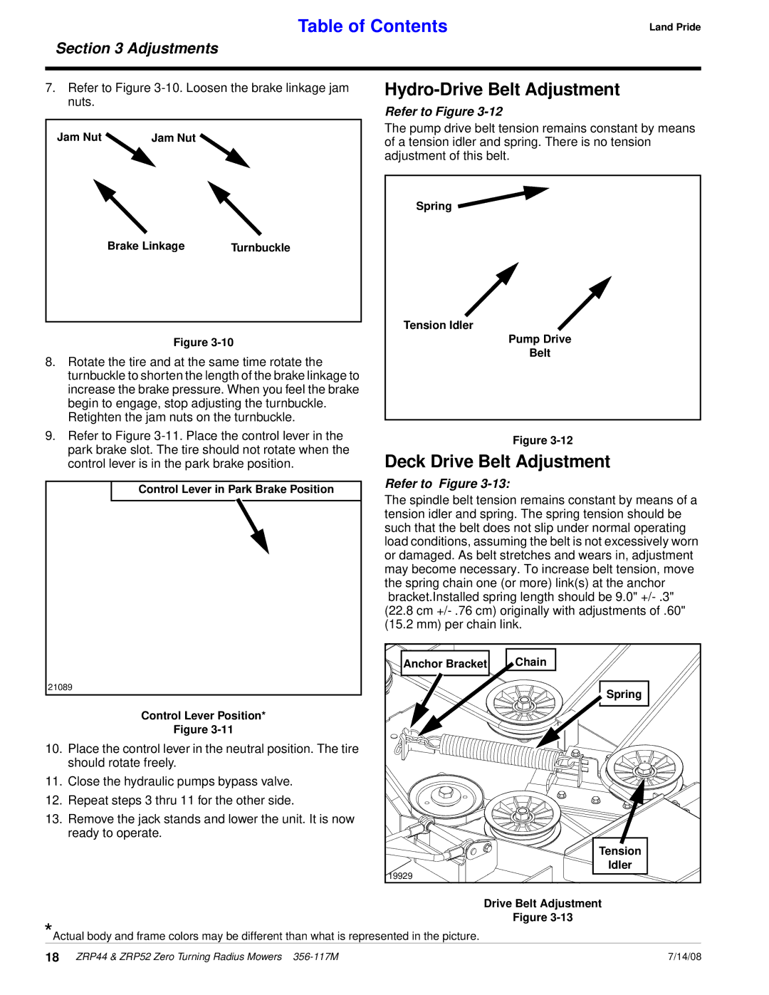
7.Refer to Figure
Jam Nut | Jam Nut |
Brake Linkage |
| Turnbuckle |
|
|
|
21073
Figure
8.Rotate the tire and at the same time rotate the turnbuckle to shorten the length of the brake linkage to increase the brake pressure. When you feel the brake begin to engage, stop adjusting the turnbuckle. Retighten the jam nuts on the turnbuckle.
9.Refer to Figure
Control Lever in Park Brake Position |
21089 |
Control Lever Position* |
Figure |
10.Place the control lever in the neutral position. The tire should rotate freely.
11.Close the hydraulic pumps bypass valve.
12.Repeat steps 3 thru 11 for the other side.
13.Remove the jack stands and lower the unit. It is now ready to operate.
Hydro-Drive Belt Adjustment
Refer to Figure 3-12
The pump drive belt tension remains constant by means of a tension idler and spring. There is no tension adjustment of this belt.
Spring
Tension Idler
Pump Drive
Belt
21090
Figure
Deck Drive Belt Adjustment
Refer to Figure 3-13:
The spindle belt tension remains constant by means of a tension idler and spring. The spring tension should be such that the belt does not slip under normal operating load conditions, assuming the belt is not excessively worn or damaged. As belt stretches and wears in, adjustment may become necessary. To increase belt tension, move the spring chain one (or more) link(s) at the anchor bracket.Installed spring length should be 9.0"
Anchor Bracket | Chain |
Spring |
Tension
Idler
19929
Drive Belt Adjustment
Figure
*Actual body and frame colors may be different than what is represented in the picture.
18 ZRP44 & ZRP52 Zero Turning Radius Mowers | 7/14/08 |
