Land Pride
Section 3 Adjustments
Table of Contents
12.Refer to Figure
13.Go to the right front of the mower.
14.Refer to Figure
15.Be sure that adjuster is free to move up and down.
16.Tighten the adjuster bolt until the chain just becomes tight, making sure that the deck stays tight against the 3” block.
17.Refer to Figure
18.Tighten the hardware holding the chain and adjuster onto the deck lift arm.
19.Go to the right rear of the mower.
20.Refer to Figure
21.Tighten the appropriate nut until the chain just becomes tight, making sure that the deck stays tight against the 3” block.
22.Tighten the other nut on the opposite side of the block, and jam them tightly together against the block.
23.Go to the left rear of the mower.
24.Refer to Figure
25.Tighten the appropriate nut until the chain just becomes tight.
26.Tighten the other nut on the opposite side of the block, and jam them tightly together against the block.
27.Refer to Figure
28.When completed, all chains will be tight, and deck cutting height will be set to the deck height indicator.
Deck Cutting Height Adjustment
Refer to Figure 3-16.
Deck height is adjustable from 1 1/2” to 4 1/2” in 1/4” increments. The holes in the height adjusting bar are spaced at 1/2” intervals. By turning the height adjusting stop around, 1/4” increments can be attained due to the 1/4” plate that is part of the stop.
EXAMPLE: When the height adjusting stop is placed in the 1 1/2” hole, with the 1/4” plate facing to the front of the unit, the cutting height is at 1 1/2”. When the height adjusting stop is placed in the 1 1/2” hole, with the 1/4” plate on the operator’s side of the hole, the cutting height is at 1 3/4”.
When the height adjusting stop is placed in one of the holes, with the 1/4” plate on the operator’s side of the hole, the deck height will be set at one of the following: 1 3/4”, 2 1/4”, 2 3/4”, 3 1/4”, 3 3/4” or 4 1/4”.
When the height adjusting stop is placed in one of the holes, with the 1/4” plate facing to the front of the unit, the deck height will be set at one of the following: 1 1/2”, 2”, 2 1/2”, 3”, 3 1/2”, 4” or 4 1/2”.
The notch located at the rear of the right height adjusting bar (4 1/2” height) is to used when the deck is placed in the transport mode.
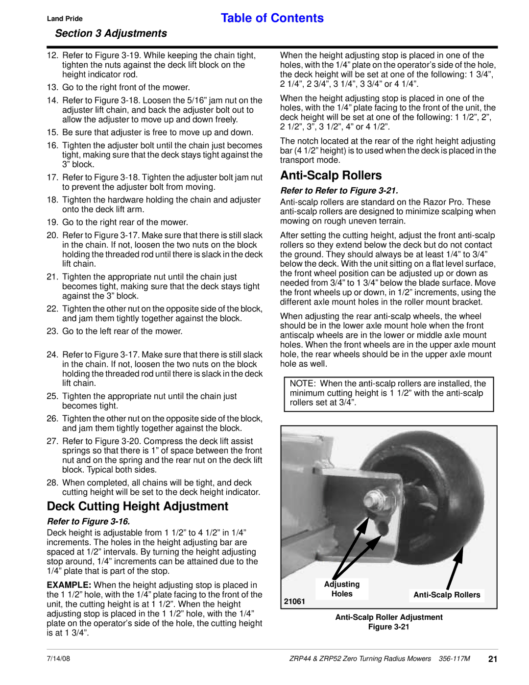
Anti-Scalp Rollers
Refer to Refer to Figure 3-21.
After setting the cutting height, adjust the front
When adjusting the rear
NOTE: When the
Adjusting |
|
Holes |
21061
Figure
7/14/08 | ZRP44 & ZRP52 Zero Turning Radius Mowers | 21 |