Land Pride
Section 3 Adjustments
Table of Contents
Control Lever Neutral Adjustment
Refer to Figure 3-2
Before considering any adjustment, check the tire air pressure and make certain hydraulic system oil is at operating temperature. Unequal tire pressure will cause the mower to drift to one side. Refer to “Tire Inflation Chart” on page 19 and page 39.
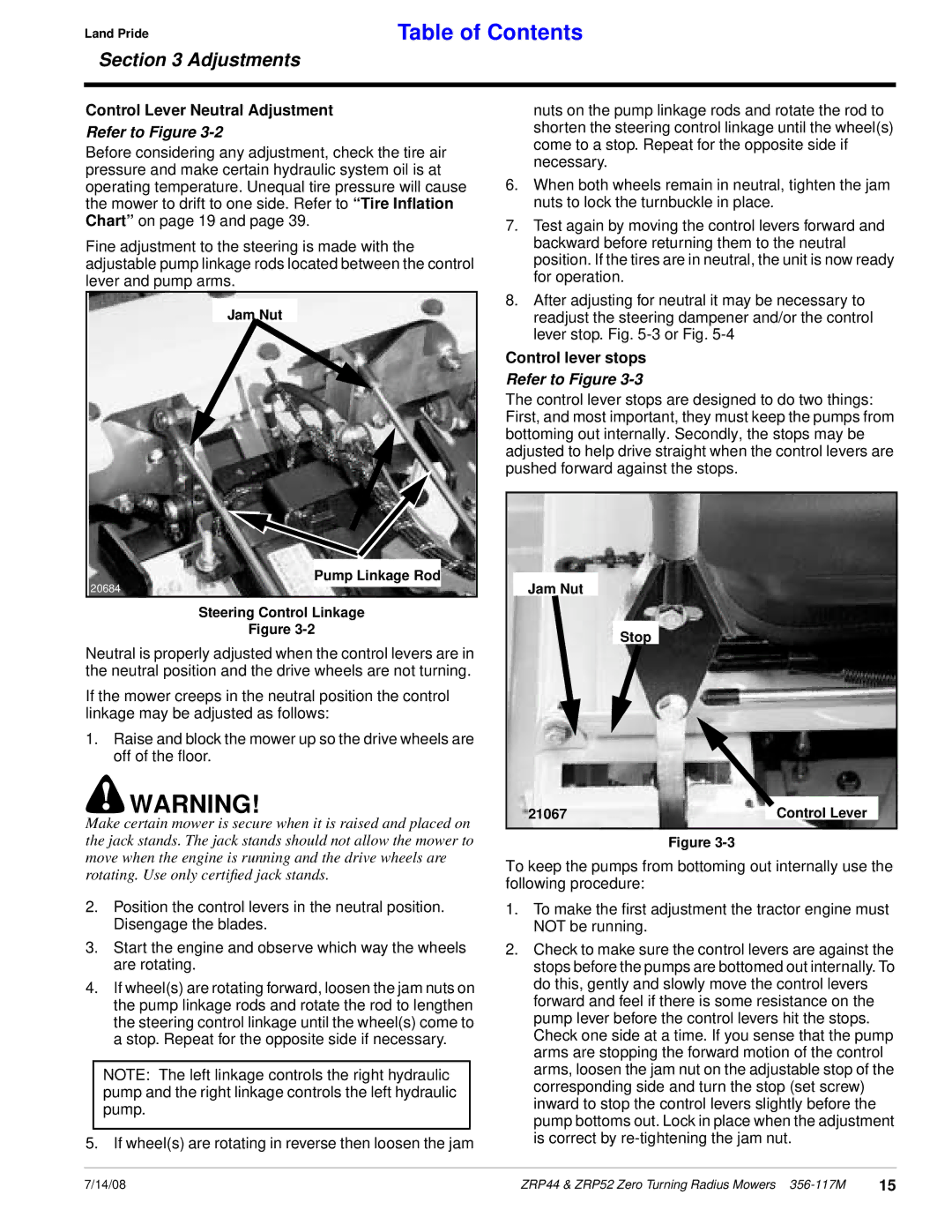
Fine adjustment to the steering is made with the adjustable pump linkage rods located between the control lever and pump arms.
Jam Nut
Pump Linkage Rod
20684
Steering Control Linkage
Figure
Neutral is properly adjusted when the control levers are in the neutral position and the drive wheels are not turning.
If the mower creeps in the neutral position the control linkage may be adjusted as follows:
1.Raise and block the mower up so the drive wheels are off of the floor.
!WARNING!
Make certain mower is secure when it is raised and placed on the jack stands. The jack stands should not allow the mower to move when the engine is running and the drive wheels are rotating. Use only certified jack stands.
2.Position the control levers in the neutral position. Disengage the blades.
3.Start the engine and observe which way the wheels are rotating.
4.If wheel(s) are rotating forward, loosen the jam nuts on the pump linkage rods and rotate the rod to lengthen the steering control linkage until the wheel(s) come to a stop. Repeat for the opposite side if necessary.
NOTE: The left linkage controls the right hydraulic pump and the right linkage controls the left hydraulic pump.
5. If wheel(s) are rotating in reverse then loosen the jam
nuts on the pump linkage rods and rotate the rod to shorten the steering control linkage until the wheel(s) come to a stop. Repeat for the opposite side if necessary.
6.When both wheels remain in neutral, tighten the jam nuts to lock the turnbuckle in place.
7.Test again by moving the control levers forward and backward before returning them to the neutral position. If the tires are in neutral, the unit is now ready for operation.
8.After adjusting for neutral it may be necessary to readjust the steering dampener and/or the control lever stop. Fig.
Control lever stops
Refer to Figure 3-3
The control lever stops are designed to do two things: First, and most important, they must keep the pumps from bottoming out internally. Secondly, the stops may be adjusted to help drive straight when the control levers are pushed forward against the stops.
Jam Nut
Stop
21067 | Control Lever |
Figure
To keep the pumps from bottoming out internally use the following procedure:
1.To make the first adjustment the tractor engine must NOT be running.
2.Check to make sure the control levers are against the stops before the pumps are bottomed out internally. To do this, gently and slowly move the control levers forward and feel if there is some resistance on the pump lever before the control levers hit the stops. Check one side at a time. If you sense that the pump arms are stopping the forward motion of the control arms, loosen the jam nut on the adjustable stop of the corresponding side and turn the stop (set screw) inward to stop the control levers slightly before the pump bottoms out. Lock in place when the adjustment is correct by
7/14/08 | ZRP44 & ZRP52 Zero Turning Radius Mowers | 15 |