Land Pride
Section 3 Adjustments
Table of Contents
NOTE: Refer to Figure
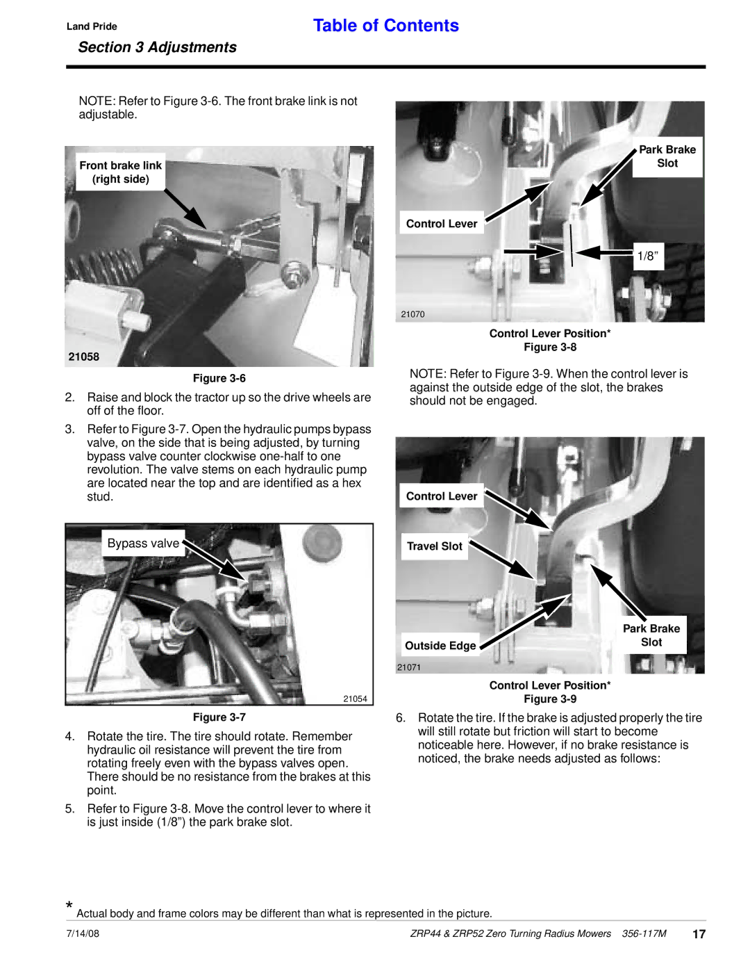
Front brake link
(right side)
Park Brake
Slot
Control Lever
![]()
![]() 1/8”
1/8”
21058
Figure
2.Raise and block the tractor up so the drive wheels are off of the floor.
3.Refer to Figure
Bypass valve 
21054
Figure
4.Rotate the tire. The tire should rotate. Remember hydraulic oil resistance will prevent the tire from rotating freely even with the bypass valves open. There should be no resistance from the brakes at this point.
5.Refer to Figure
21070
Control Lever Position*
Figure
NOTE: Refer to Figure
Control Lever
Travel Slot
|
| Park Brake |
Outside Edge |
| Slot |
|
| |
|
|
|
|
|
|
21071
Control Lever Position*
Figure
6.Rotate the tire. If the brake is adjusted properly the tire will still rotate but friction will start to become noticeable here. However, if no brake resistance is noticed, the brake needs adjusted as follows:
*Actual body and frame colors may be different than what is represented in the picture.
7/14/08 | ZRP44 & ZRP52 Zero Turning Radius Mowers | 17 |