Land Pride | Table of Contents |
Section 1 Assembly and Set-Up
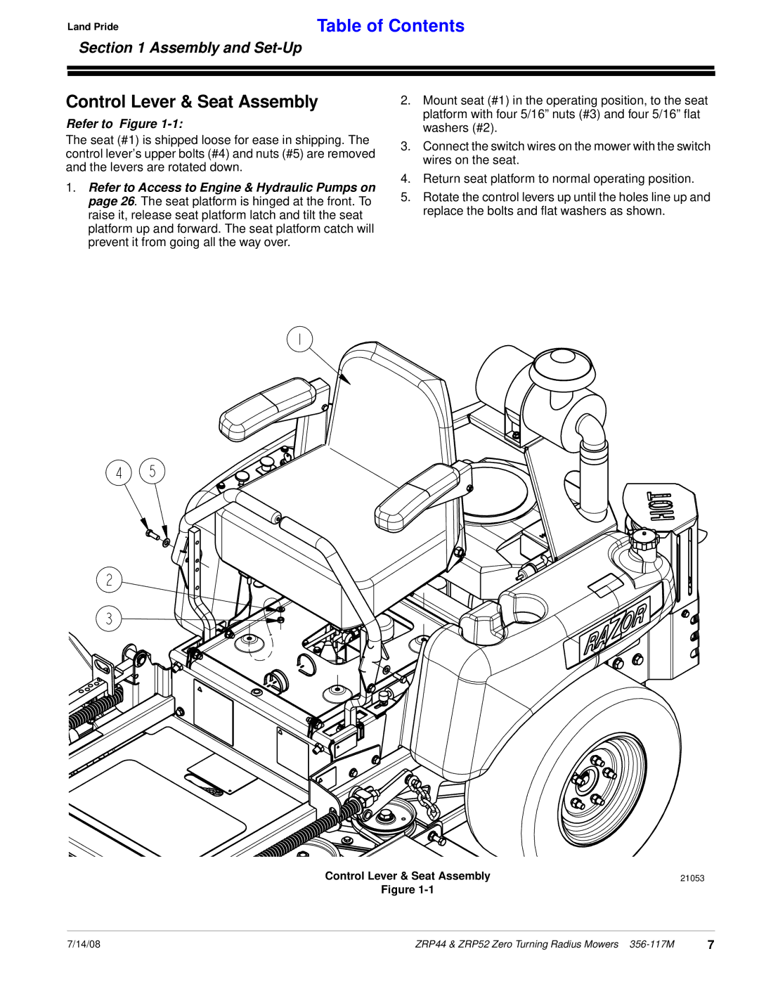
Control Lever & Seat Assembly
Refer to Figure 1-1:
The seat (#1) is shipped loose for ease in shipping. The control lever’s upper bolts (#4) and nuts (#5) are removed and the levers are rotated down.
1.Refer to Access to Engine & Hydraulic Pumps on page 26. The seat platform is hinged at the front. To raise it, release seat platform latch and tilt the seat platform up and forward. The seat platform catch will prevent it from going all the way over.
2.Mount seat (#1) in the operating position, to the seat platform with four 5/16” nuts (#3) and four 5/16” flat washers (#2).
3.Connect the switch wires on the mower with the switch wires on the seat.
4.Return seat platform to normal operating position.
5.Rotate the control levers up until the holes line up and replace the bolts and flat washers as shown.
Control Lever & Seat Assembly | 21053 |
Figure
7/14/08 | ZRP44 & ZRP52 Zero Turning Radius Mowers | 7 |